


Military-Grade Intelligent Fan Drives for Defense Thermal Management
Closed-Loop PWM Regulation, Multi-Protocol Telemetry, and Fail-Safe Fan Control
Perseus intelligent fan drives coordinate PWM speed control, telemetry, and fault behavior for rugged cooling assemblies. Designed around Perseus fans, these architectures support temperature-driven control, host-commanded profiles, multi-zone feedback, and fail-safe cooling states for avionics, radar, naval, and ground electronics.
Core Technical Features
Closed-Loop Fan Speed Regulation:
Temperature-driven or host-commanded PWM control adjusts airflow to thermal load, reducing unnecessary full-speed runtime while preserving cooling margin.
Native Perseus Fan Compatibility:
Drive profiles align startup, PWM response, FG/RD feedback, rotor-lock reporting, and rated operating-point behavior with Perseus fan assemblies.
Multi-Protocol Integration:
RS232, RS485, CAN bus, Ethernet, and I2C options support enclosure controllers and platform health-monitoring systems.
Fail-Safe Cooling Behavior:
On communication loss or alarm conditions, the drive can default to a defined safe cooling state and report fan faults for maintenance review.
Typical Applications
-
![]()
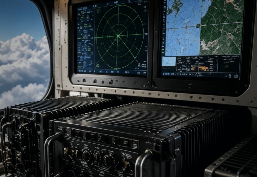
Controls fan speed in avionics boxes and radar processors where thermal margin, acoustic load, and power budget must be balanced.
Avionics LRUs and Radar Processors
-
![]()
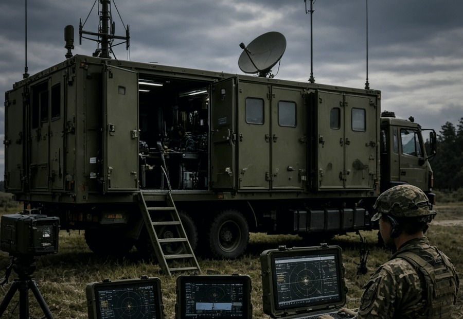
Coordinates multiple fan zones in rugged shelters and vehicle electronics with fault telemetry for maintenance review.
C4ISR Shelters and Ground Electronics
-
![]()
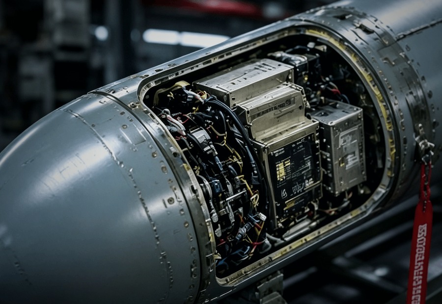
Supports continuous cooling in naval cabinets where EMC-aware integration and stable fan behavior matter near communications equipment.
Shipboard and Naval Electronics
-
![]()
Preserves voltage, airflow, alarm logic, and control behavior when obsolete cooling assemblies are replaced.
Form-Fit-Function Cooling Retrofits

Series Selection Guide
Multi-Channel Fan Drives
| Feature | Specification | Engineering Notes |
|---|---|---|
| Fan Capacity | Up to 8 fans | Multi-zone cooling control |
| Primary Interfaces | RS232 / RS485 / CAN bus | Host control and fault reporting |
| Control Modes | PWM speed control | Temperature-driven, host-commanded, or fixed profile |
| Diagnostics | Rotor-lock fault reporting | Fan health status by configuration |
| Qualification Planning | MIL-STD-810H / MIL-STD-461G references | Final limits by platform plan |
Network-Enabled Fan Drives
| Feature | Specification | Engineering Notes |
|---|---|---|
| Fan Capacity | Up to 6 fans | Distributed thermal-zone control |
| Primary Interfaces | Ethernet / I2C / CAN / RS485 | Enclosure or platform controller integration |
| Sensor Inputs | Up to 4 thermistor channels | Multi-zone thermal mapping |
| Telemetry | Current / voltage / temperature / fault status | Maintenance and health review |
| Use Case | C4ISR, naval electronics, radar processors | Networked thermal-management systems |
Compact and Integrated Smart Fan Drives
| Feature | Specification | Engineering Notes |
|---|---|---|
| Fan Capacity | 1-3 fans | Space-constrained LRUs |
| Input Voltage | 9-36 VDC | Source range from existing documentation |
| Quiescent Power | <0.5 W | Standby or low-load thermal states |
| Control Options | NTC / manual override / RS485 | Thermostatic, manual, or remote-control variants |
| Smart Assembly Modes | 3-speed / 0-100% proportional / temperature-driven | Sealed plug-and-play modules by configuration |
Motors & Drives Overview
Perseus Motors & Drives focuses on intelligent fan-drive architectures for defense thermal management. These controllers coordinate PWM speed control, telemetry, and fault behavior for Perseus fan assemblies in avionics, radar, naval, and ground electronics.
Architecture options include multi-channel drives for up to 8 fans, network-enabled drives for up to 6 fans, and compact 1-3 fan controllers with 9-36 VDC input. Interfaces can include RS232, RS485, CAN bus, Ethernet, and I2C. Environmental and EMC planning can reference MIL-STD-810H Method 514.8 / 516.8 and MIL-STD-461G CE102 / RE102 according to the final platform test plan.
- Drive scope
Confirm fan count, cooling zones, and required fail-safe state.- Electrical interface
Share voltage bus, communication protocol, and sensor layout.- Qualification context
Define vibration, shock, EMC, and acceptance limits by platform plan.