High-Reliability Thermal Solutions for Semiconductor Manufacturing Equipment

Built for Process Temperatures up to 150°C, Cleanroom Environments, and Zero Unplanned Downtime

Semiconductor Cooling | CVD | ALD | Diffusion Furnace | Epitaxy | Lithography | Ion Implant | CMP | Cleanroom | High-Temp Bearing | Wafer Handling | Fab Uptime | Thermal Management

Solution Overview

Semiconductor fabrication demands thermal management precision that no other industry requires. Process chambers in CVD, ALD, diffusion furnace, and epitaxy systems operate at sustained temperatures up to 150°C, while lithography environments require temperature stability within ±0.1°C to maintain nanometer-scale pattern fidelity. Any cooling system vibration, contamination, or unplanned downtime directly translates into wafer yield loss and production line stoppages worth millions per hour.

Our fan assemblies and thermal management solutions are engineered specifically for the semiconductor manufacturing chain—from high-temperature process chamber circulation to cleanroom FFU systems, exhaust abatement, and precision wafer-handling environments. Utilizing heat-treated bearing systems, low-vibration dynamic balancing, and cleanroom-compatible materials, our products deliver continuous operation across the full process temperature envelope while protecting the mechanical integrity of sensitive automation and wafer transport systems.

Application Scenarios

  • Epitaxy & Diffusion Furnace

    Heat-treated bearing assemblies sustain continuous airflow in process chambers up to 150°C, preventing seizure across extended high-temperature wafer processing cycles.
  • CVD & ALD Chamber Cooling

    Cleanroom-compatible fan materials deliver precise thermal management for thin-film deposition chambers, maintaining wafer-to-wafer temperature uniformity and process repeatability.
  • UV-CVD & Photochemical Processing

    Low-vibration fan systems maintain stable UV light source temperatures, ensuring consistent photochemical reaction conditions and film quality throughout the deposition process.
  • Lithography Environment Control

    Precision-balanced airflow maintains thermal stability within ±0.1°C across exposure fields, protecting nanometer-scale pattern fidelity without disturbing optical alignment systems.
  • Ion Implantation Cooling

    Continuous thermal management for implanter beam components prevents temperature drift that degrades dopant profile accuracy across high-dose production runs.
  • CMP Tool Thermal Control

    Stable cooling for CMP electronics and slurry temperature systems ensures consistent material removal rate uniformity and within-wafer planarity across production volumes.
  • Cleanroom FFU & Air Circulation

    High-reliability, low-noise fan systems for Fan Filter Units maintain ISO Class 1–5 particulate control without introducing vibration to adjacent precision equipment.
  • Exhaust Abatement & Gas Scrubbing

    Chemically resistant sealed blower assemblies handle toxic and corrosive process gases from CVD, etch, and implant tools reliably in aggressive exhaust environments.
  • Wafer Handling & FAB Automation

    CMM-verified dynamic balancing eliminates vibration-induced disturbance to wafer transport robots and AMHS systems, protecting positioning accuracy at nanometer scale.

Core Challenges

  • Extreme Thermal Resilience:Specifically designed for epitaxy equipment and industrial furnace environments. Utilizing specialized heat-treated bearings and aluminum alloy frames, our fans sustain continuous operation in high-temp cycles without seizure.
  • Precision & Stability:Rigorous dynamic balancing and CMM testing ensure minimal mechanical vibration. This precision is critical for protecting the structural integrity of sensitive FAB automation and wafer-handling systems.

How we solve it


Frequently AskedQuestions (FAQ)

  • Why do high-impedance ducts or fin stacks need static-pressure-focused fan selection?
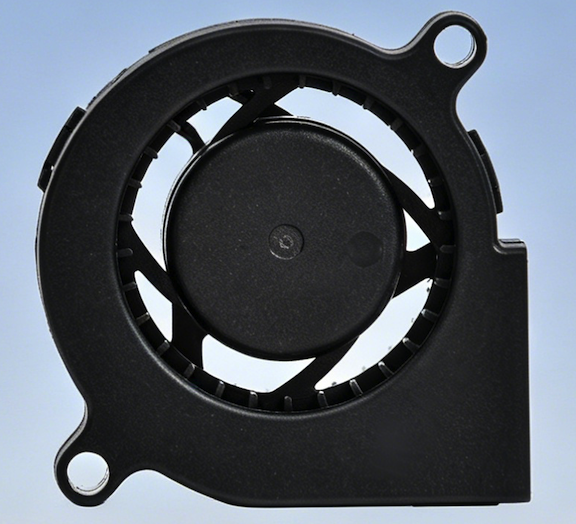
    A: Free-air CFM is measured at zero static pressure and is not the airflow delivered inside a dense enclosure. Heat sinks, filters, louvers, long ducts, and tight VPX/CPCI card cages create system resistance. The real airflow is the intersection of the fan P-Q curve and the system impedance curve. Centrifugal fans are often a better fit for high-impedance paths because they maintain pressure through narrow or redirected airflow channels, while axial fans are better for lower-resistance, direct-through cooling. 
  • Why does airflow drop after long operation in dusty, humid, or high-temperature equipment?
    A: Long-term airflow loss usually comes from one of four causes: inlet or outlet blockage, voltage drop at the fan terminals, incorrect PWM command, or mechanical degradation. Dust and process residue increase system impedance, humidity and salt can raise connector resistance, and high temperature accelerates lubricant and bearing wear. Troubleshooting should record terminal voltage, current draw, PWM duty cycle, FG speed, inlet condition, outlet condition, and any abnormal bearing noise before replacing the fan. 
  • How long do Perseus fans last in high-temperature duty?
    A: Service life depends on bearing load, speed, temperature, humidity, vibration, and contamination. Representative Perseus DC fan models list L10 life of 50,000 hours at 40°C, while the Titan 400Hz AC reference model lists L10 life of 13,000 hours at 40°C. For semiconductor or furnace-adjacent duty, review lubricant temperature limit, bearing type, airflow path cleanliness, and the actual chamber-side ambient before using any catalog life value. 
  • Which fan materials are best for salt fog, cleanrooms, and airborne weight targets?
    A: Material choice should follow the failure mode. Aluminum alloy housings improve rigidity, heat spreading, and vibration resistance for airborne, naval, and tracked-vehicle systems. PPO or engineered polymer configurations reduce weight and support corrosion resistance where the mechanical load is lower. For salt fog, specify coating, fastener material, bearing sealing, and MIL-STD-810H Method 509.7 exposure. For cleanroom equipment, review particle shedding, lubricant volatility, and surface treatment rather than choosing only by frame material. 
  • How do I estimate required airflow from heat load before pressure drop is known?
    A: Start with heat load, allowable temperature rise, and air properties. A practical first-pass estimate is airflow equals heat load divided by air density, specific heat, and allowed temperature rise. Using 1.225 kg/m3 air density and 1,004 J/kg-K specific heat, a 400 W load with a 10°C rise needs about 117 m3/h before pressure-loss margin. If the enclosure pressure drop is unknown, select an initial fan target around 1.3 to 2.0 times the calculated airflow, then verify the operating point with P-Q data.