

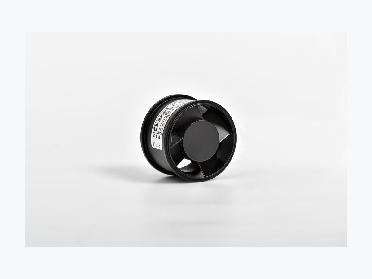
Titan PCG67JFZY722-63G-AA
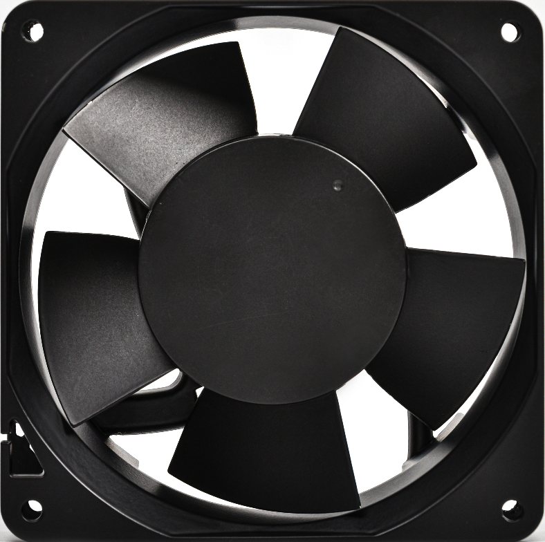
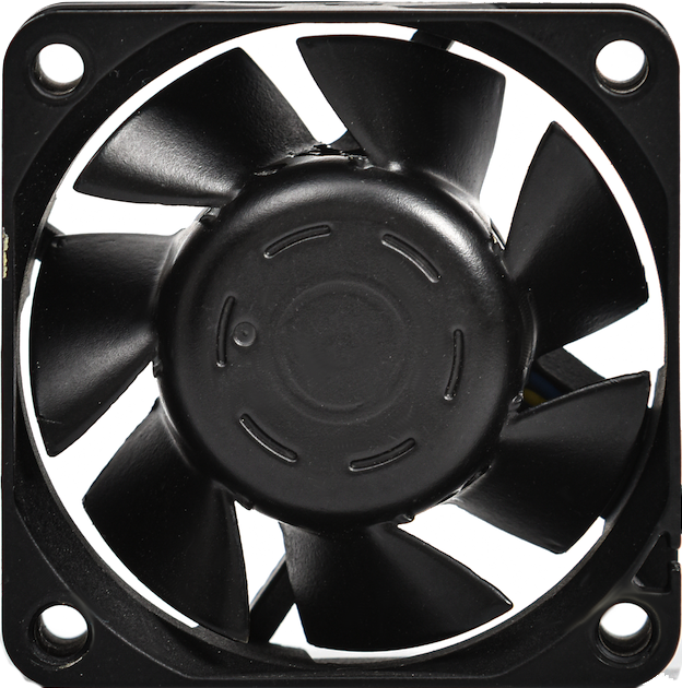
Dia. 76.2mm x 65.5mm Frame
200V / 115V AC, 400Hz Platform


Civil Aviation | Avionics Cooling | DO-160G | Model-Specific Reliability Review | Low Noise | FFF Replacement | APU Cooling | IFE | Cargo Thermal Control | High Altitude | Cabin Comfort | E-Bay Cooling
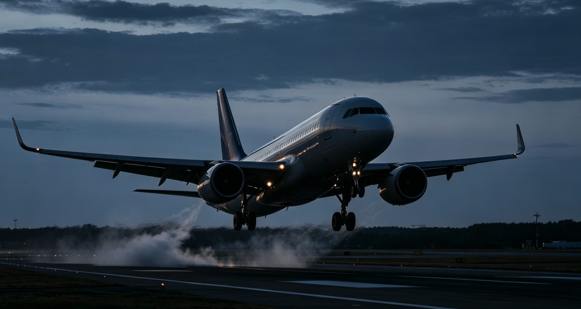
Commercial aircraft operate across the most demanding thermal environments in civilian engineering—from -55°C cold-soak at cruise altitude to +85°C ground operations in tropical climates, at cabin pressures equivalent to 8,000 feet and altitudes reaching 49,000 feet where air density drops significantly. Every fan failure in this environment carries direct consequences for flight safety, passenger comfort, and aircraft dispatch reliability.

Our thermal management solutions cover the full aircraft architecture—from flight deck avionics bays and APU enclosures to passenger cabin ventilation, galley exhaust, and cargo compartment environmental control. All systems are designed for program-specific review against RTCA DO-160G environmental and electrical test sections where required, with precision dual ball bearing assemblies delivering model-specific reliability evidence and bearing-life review supplied with the qualification package. For fleet operators, we provide exact Form-Fit-Function (FFF) drop-in replacements that eliminate airframe modifications and minimize Aircraft on Ground (AOG) downtime.
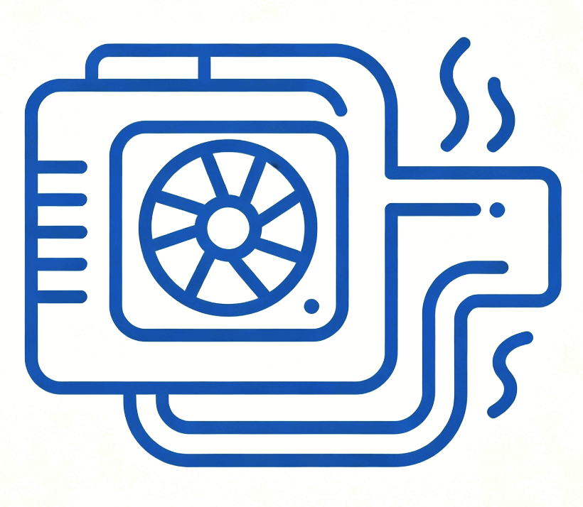
Primary forced-air cooling for flight control computers, navigation suites, and communication systems housed in forward and aft avionics equipment bays. Maintains thermal stability across all flight phases from cold-soak taxi to high-density cruise operations.
Dedicated low-noise ventilation for instrument panels, circuit breaker panels, and display processors on the flight deck. Acoustic performance below 28 dB(A) supports low-noise integration near crew communication and situational-awareness systems.
High-flow cooling for APU starter-generator enclosures and associated power electronics during ground operations and in-flight auxiliary power generation. Validated for continuous operation across the full ground-to-cruise temperature envelope.
High-flow ventilation for wheel-well electronics and brake assembly thermal management following high-energy landing events. Rapid heat dissipation reduces brake turnaround time and extends brake service life for high-frequency short-haul operations.
High-reliability exhaust fan systems for galley equipment bays and lavatory ventilation, designed for continuous duty cycle operation with acoustic signatures optimized for passenger cabin comfort throughout all flight phases.
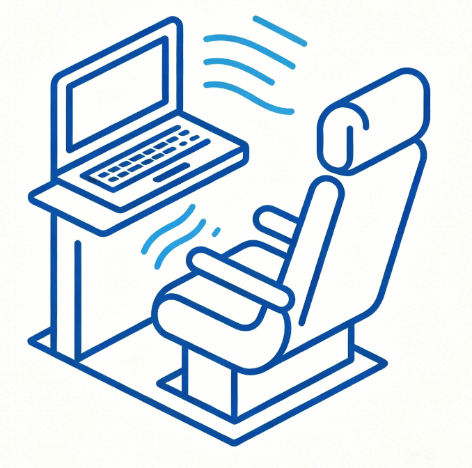
Ultra-low-noise cooling for under-seat IFE processors, seat control units, and power distribution boxes. Acoustic-optimized impeller designs ensure passenger comfort while maintaining reliable thermal management for high-density seat electronics.
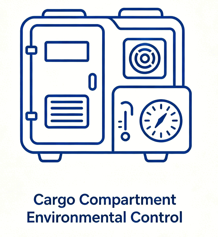
Airflow solutions for temperature-sensitive cargo and live animal transport in pressurized cargo bays. Humidity-resistant fan assemblies validated to DO-160G maintain consistent compartment temperatures regardless of external ambient conditions or flight altitude.
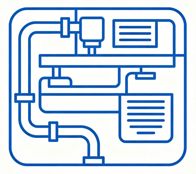
Thermal management for solid-state power controllers, bus power control units, and transformer rectifier units throughout the aircraft electrical distribution architecture. Supports both conventional and More Electric Aircraft (MEA) power system configurations.
Exact Form-Fit-Function drop-in replacements for legacy fan assemblies across wide-body, narrow-body, and regional aircraft platforms. Identical mechanical dimensions and P-Q performance curves eliminate airframe modifications, reducing Aircraft on Ground (AOG) downtime to a minimum.
1. High-Static-Pressure Impeller Design for High-Altitude Performance:
At cruise altitude, reduced air density causes standard fans to deliver insufficient mass airflow for avionics cooling, while low pressure creates arcing risks in unprotected motor windings. Our high-static-pressure impeller profiles are engineered to maintain consistent mass airflow at altitudes up to 49,000 ft, while Vacuum Pressure Impregnation (VPI) with aerospace-grade dielectrics helps reduce arcing risk when insulation and pressure conditions are validated—delivering full thermal performance from sea level to specified altitude profile with derating reviewed against the platform pressure profile.

2. Aero-Acoustic Optimization for Cabin & Cockpit Environments:
Passenger comfort and crew performance depend on cooling systems that operate below strict acoustic thresholds across all flight phases. Our low-turbulence aerodynamic blade designs and precision dynamic balancing achieve noise signatures below 28 dB(A) at 1 meter, while DO-160G shock and vibration validation ensures structural integrity through continuous turbulence and hard landing events—meeting both acoustic certification requirements and long-term mechanical reliability targets simultaneously.

3. FFF Drop-In Replacement for Zero-Modification Fleet Integration:
Legacy fan obsolescence forces operators into costly airframe modification programs that extend AOG downtime and drive up maintenance costs. Our exact Form-Fit-Function replacements match the mechanical dimensions, connector interfaces, and P-Q performance curves of original equipment across wide-body, narrow-body, and regional platforms—enabling immediate installation with zero airframe modifications, reducing AOG resolution time from days to hours.

4. Long-Life Reliability for Extended Maintenance Intervals:
Frequent fan replacement drives up maintenance labor costs and increases AOG exposure for high-utilization commercial fleets. Our precision dual ball bearing assemblies are engineered to achieve model-specific reliability evidence and bearing-life review supplied with the qualification package, aligning with heavy maintenance check intervals and reducing the likelihood of unscheduled fan replacement when operating conditions match the qualification plan—reducing total lifecycle cost across the entire fleet.
| Cooling Method | Altitude Performance | Acoustic Impact | AOG Compatibility | Best For |
|---|---|---|---|---|
| Forced-Air Convection (High-Static-Pressure) | Rated to 49,000 ft | <28 dB(A) optimized | FFF Drop-in Available | Avionics bays, cockpit, IFE, galley |
| Conduction-Cooled (Chassis-Integrated) | Altitude-independent Zero | Zero airborne noise | Custom integration required | Sealed avionics modules, line-replaceable units |
| Liquid-Cooled (Closed Loop) | Altitude-independent | Zero airborne noise | System-level modification | High-power radar processors, MEA power electronics |