


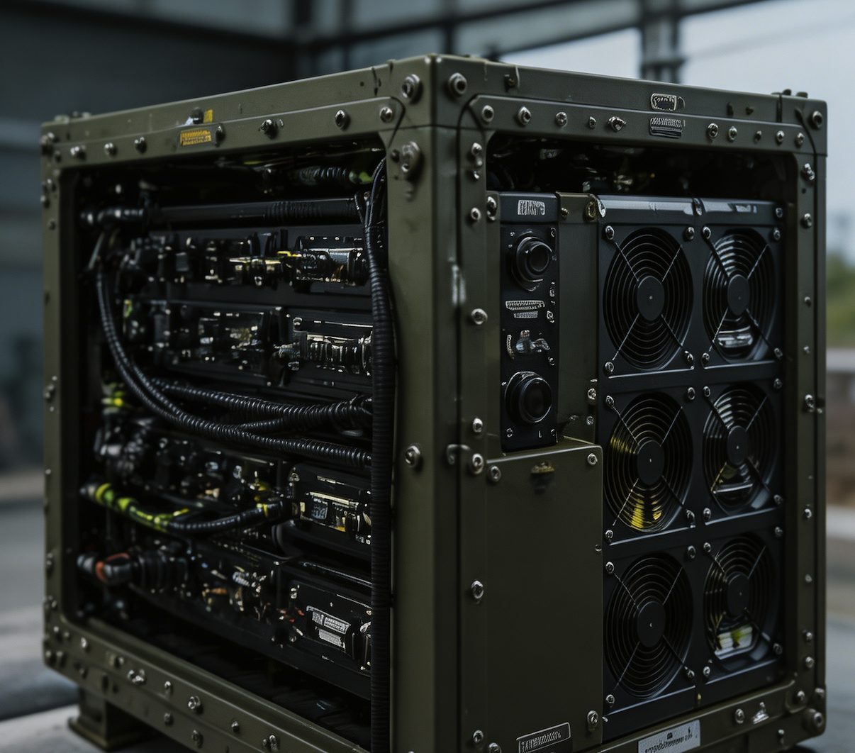
Military Centrifugal Blowers & Radial Cooling Fans
Consistent static pressure through high-impedance ducted systems, directed-energy weapon enclosures, and complex defense electronic packaging.
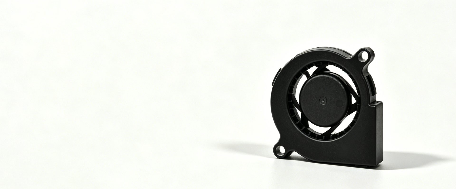
Axial fans are efficient — until the airflow path bends, narrows, or runs through a long duct. At that point, static pressure drops and cooling capacity falls faster than most system designers expect. This is the fundamental problem centrifugal fans solve.


Unlike axial fans that lose static pressure rapidly as system resistance increases, the Perseus radial impeller maintains near-constant pressure output across the operating range. In practice, this means reliable cooling through radar ducts with multiple 90° bends, shipboard console displays with restricted internal layouts, and electro-optic housings where the heat source is buried deep inside the assembly — exactly where static pressure matters most.
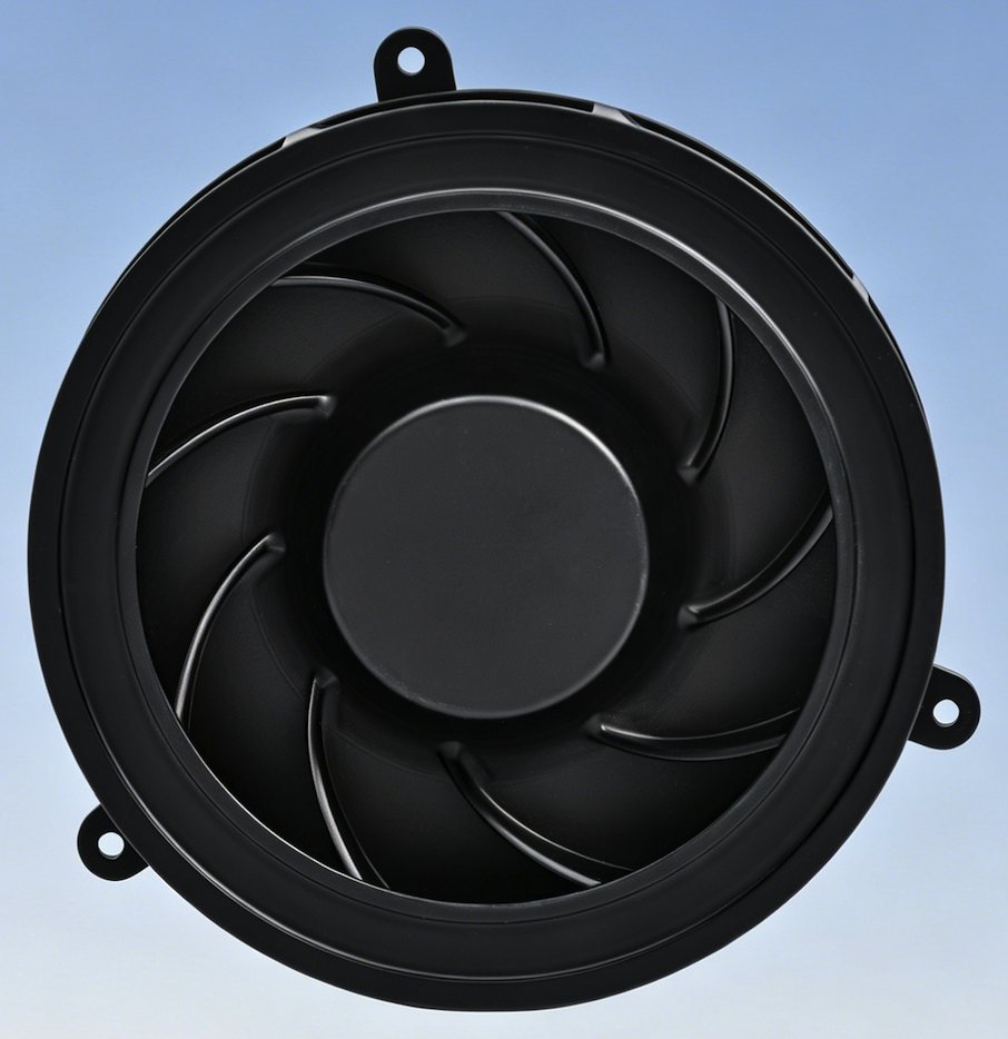
Core Technical Features
Radial Impeller Geometry:
Engineered to generate consistent static pressure required for high-impedance ducted systems.
Stable Pressure in Constraints:
Delivers precise cooling to specific heat sources within densely packed electronics where airflow paths are restricted.
Ruggedized Hardened Housing:
Specifically built to withstand mechanical shock and vibration per MIL-STD-810 standards.
Compact Space Optimization:
Frame sizes from 50mm to 150mm are ideal for airborne radar modules and shipboard console displays.
Typical Applications
-
![]()
Radar cooling ducts with multiple bends and extended runs create system impedance that reduces axial fan output significantly. The Prometheus and Atlas series maintain static pressure through these configurations — delivering cooling to heat sources that would otherwise receive insufficient airflow.
High-Resistance Ducted Airflow Systems
-
![]()
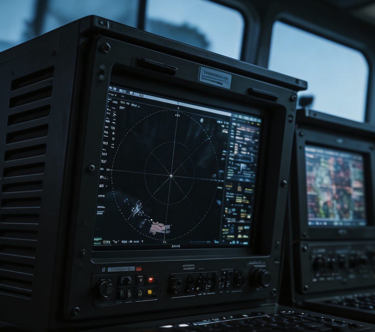
Naval console displays generate heat in spatially constrained housings with restricted internal airflow paths. The compact Prometheus series fits within display enclosure depth constraints while delivering the directed airflow needed to prevent processor thermal throttling during sustained operations.
Shipboard Console Display Cooling
-
![]()
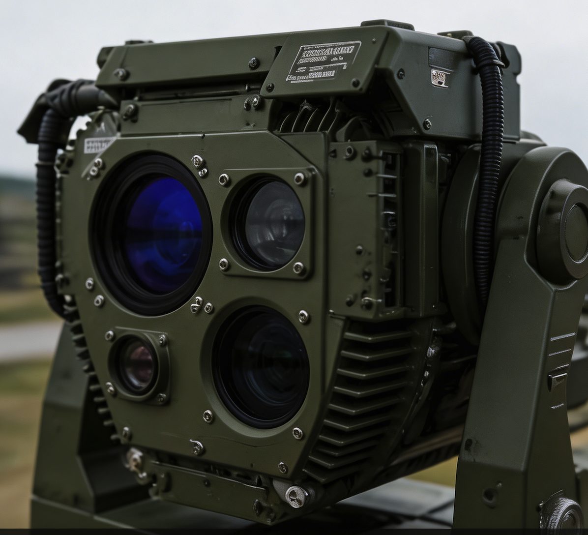
EO/IR systems house imaging sensors and signal processors in sealed enclosures where heat must be extracted from specific components without affecting adjacent optical paths. The IP68-rated centrifugal configurations handle both the thermal and sealing requirements within the same compact housing.
Electro-Optic System Thermal Control
-
![]()
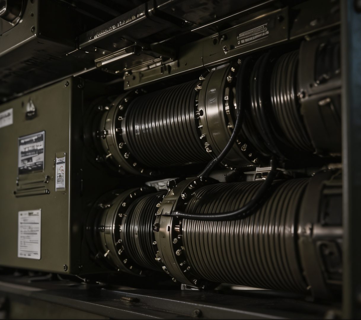
Dense VPX and CPCI chassis with multiple card slots, power supplies, and interconnects create tortuous airflow paths that require sustained static pressure to maintain adequate cooling across all installed modules — a requirement that centrifugal geometry is specifically suited to meet.
Rugged VPX / CPCI Chassis Cooling
Series Selection Guide
| Series | Frame Size | Max Airflow (CFM) | Power Range (W) |
|---|---|---|---|
| Prometheus | 50–100mm | 45.96 | 1.35–18.24 |
| Atlas | 100–150mm | 150.93 | 8.40–25.44 |
Model Reference
Model
Atlas PCG150FLW43-32G
150mm x 150mm x 32mm Frame
24V DC Platform
Expand content

Core Electrical & Performance Parameters
| Parameter | Specification |
|---|---|
| Rated Voltage | 24V DC |
| Voltage Range | 18-26.5V DC |
| Operating Current (Free Air) | 1.25A |
| Rated Power (Free Air) | 30.00W |
| Rated Rotational Speed | 3,700 RPM +/-10% |
| Max Airflow | 150.93 CFM / 256.28 m3/h |
| Max Static Pressure | 29.15 mmH2O / 285.67 Pa |
| Acoustic Noise | 62.5 dB(A), Max 65.5 dB(A) |
| Speed Control Mode | PWM |
| Output Signal | RD (Rotation Detector) |
| Rotation Direction | Clockwise, viewed from impeller side |
Mechanical & Environmental Parameters
| Parameter | Specification |
|---|---|
| Frame Size | 150mm x 150mm x 32mm |
| Frame / Impeller Material | Aluminum alloy or PBT configuration; final material by selected variant |
| Bearing Type | Dual ball bearing |
| Weight | 440g |
| Protection Rating | IP68 configuration option |
| Lead Interface | Shielded WFA1142-24 power, RD, and PWM leads |
| Insulation Resistance | >=10MOhm at 500V DC, frame-to-lead |
| Dielectric Withstand | <1mA at 500V DC, frame-to-lead |
| L10 Life | >=50,000h at 40C, 15-65% RH |
| Operating Temperature Range | -40C to +60C |
| Storage Temperature Range | -55C to +70C |
| Salt Fog Exposure | Salt-fog exposure profile listed in source requirements |
| Humidity Exposure | 30C to 60C, 95% +/-5% RH, 10 cycles of 24h |
| Rain Exposure | 6mm / 12h rain exposure profile |
| Sand & Dust Exposure | Dust and sand blowing exposure profile |
| Vibration Exposure | Wheeled-vehicle vibration profile listed in source requirements |
| EMC Planning Reference | MIL-STD-461G CE102 / RE102 planning reference; final limits by platform test plan |
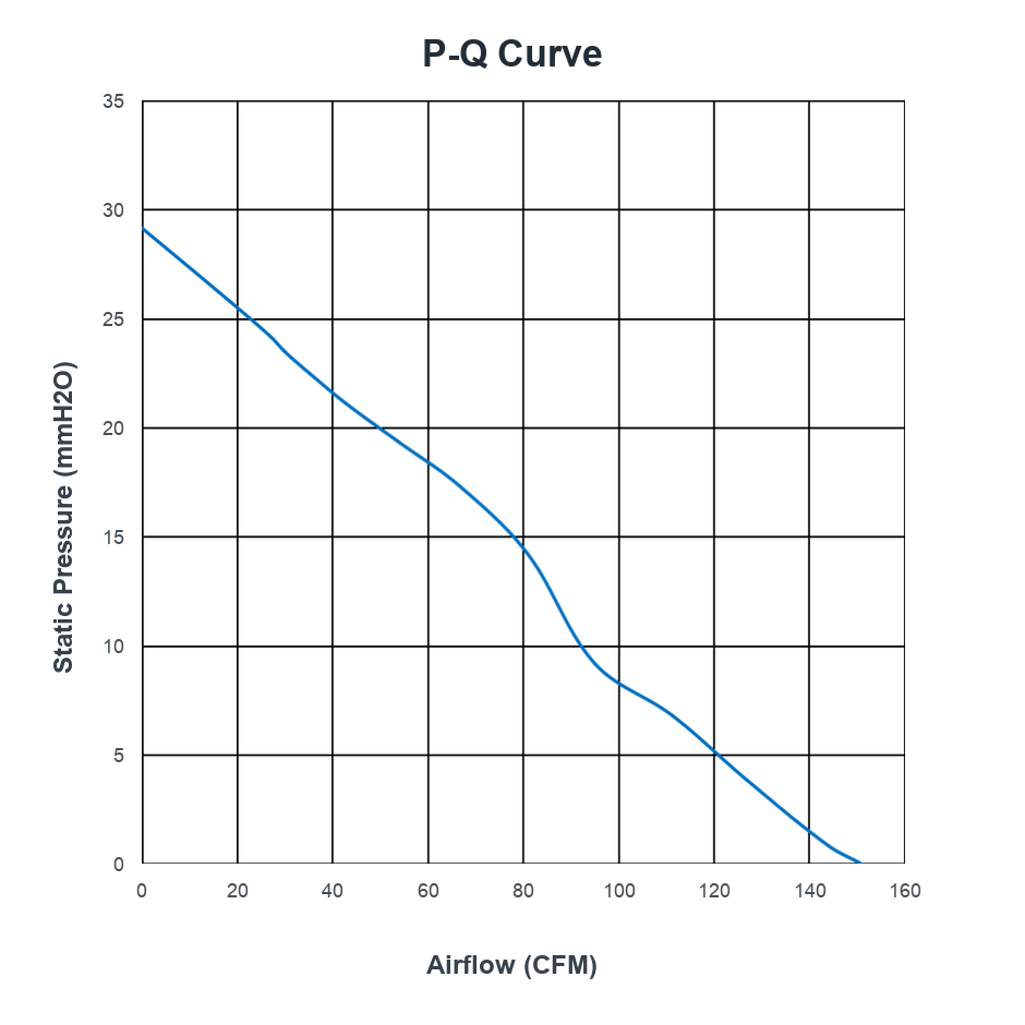
P-Q Curve — PCG150FLW43-32G @ 24V DC
At nominal input conditions, this reference curve maps static pressure from 0-29.15 mmH2O against airflow from 0-150.93 CFM. Use it for first-pass operating-point review; full-resolution P-Q curves, CAD files, and product-specific datasheets are available for qualified RFQ review.
Model
Prometheus PCG38FLW312-20G-AB
50mm x 50mm x 20mm Frame
12V DC Platform
Expand content
Core Electrical & Performance Parameters
| Parameter | Specification |
|---|---|
| Rated Voltage | 12V DC |
| Voltage Range | 10-13.5V DC |
| Operating Current (Free Air) | 0.50A |
| Rated Power (Free Air) | 6.00W |
| Rated Rotational Speed | 12,000 RPM +/-10% |
| Max Airflow | 9.2 CFM / 15.6 m3/h |
| Max Static Pressure | 37.2 mmH2O / 364.5 Pa |
| Acoustic Noise | 58.5 dB(A), Max 61.5 dB(A) |
| Speed Control Mode | PWM |
| Output Signal | FG (Frequency Generator) |
| Rotation Direction | Counterclockwise, viewed from impeller side |
Mechanical & Environmental Parameters
| Parameter | Specification |
|---|---|
| Frame Size | 50mm x 50mm x 20mm |
| Frame / Impeller Material | Aluminum alloy or PBT configuration; final material by selected variant |
| Bearing Type | Dual ball bearing |
| Weight | 65g |
| Protection Rating | IP68 configuration option |
| Lead Interface | AWG26 power, FG, and PWM leads; >300mm lead length |
| Insulation Resistance | >=10MOhm at 500V DC, frame-to-lead |
| Dielectric Withstand | <1mA at 500V DC, frame-to-lead |
| L10 Life | >=50,000h at 40C, 15-65% RH |
| Operating Temperature Range | -55C to +85C |
| Storage Temperature Range | -55C to +90C |
| Salt Fog Exposure | 192h acidic salt spray profile |
| Humidity Exposure | 95% +/-5% RH, 10 cycles of 24h |
| Rain Exposure | Intensified rain exposure, 40min per side |
| Sand & Dust Exposure | Dust and sand blowing exposure profile |
| Mechanical Shock | 30g peak, 11ms sawtooth, 18 total shocks |
| Acceleration | 9g performance / 13.5g structural profile |
| Temperature Shock | -55C to +85C, transfer time <1min, 3 cycles |
| EMC Planning Reference | MIL-STD-461G CE102 / RE102 planning reference; final limits by platform test plan |
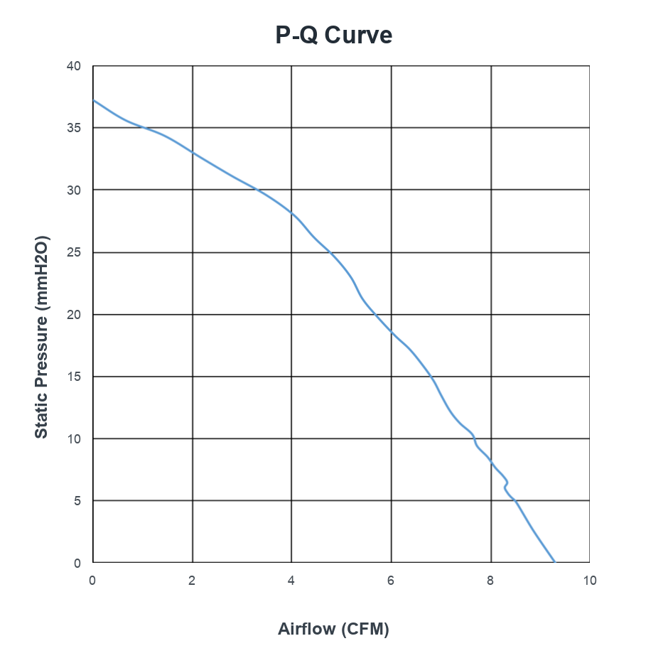
P-Q Curve — PCG38FLW312-20G-AB @ 12V DC
At nominal input conditions, this reference curve maps static pressure from 0-37.2 mmH2O against airflow from 0-9.2 CFM. Use it for first-pass operating-point review; full-resolution P-Q curves, CAD files, and product-specific datasheets are available for qualified RFQ review.
Full-resolution PQ curves, CAD models (STEP/IGES), and complete datasheets for all models are available upon RFQ
This reference covers one model in one frame size. The full Prometheus / Atlas library includes validated configurations across 50mm–150mm frames, with custom voltage (DC 5–48V), airflow, and connector options