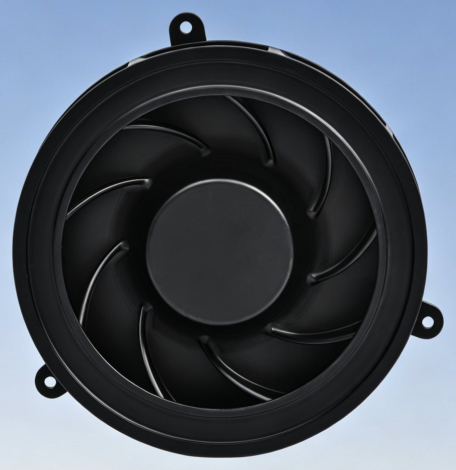
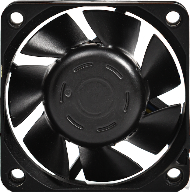
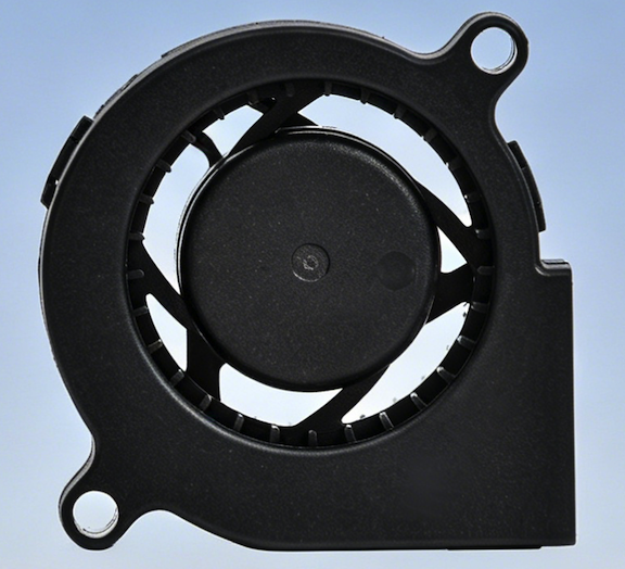
Thermal Management for Next-Gen Radar & Electronic Warfare

Engineered for Extreme Heat Dissipation, EMI Stealth, and Mission-Critical Reliability.

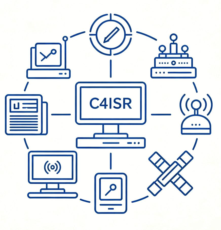
AESA Radar Cooling  |  Military Thermal Management  |  T/R Module Cooling  |  High-Altitude Cooling

Solution Overview

Modern AESA radar systems and electronic warfare (EW) suites face a critical thermal challenge: T/R modules generate concentrated heat in confined spaces where traditional cooling architectures can lose margin. High-power RF components may operate from -55°C cold conditions to elevated desert ambient temperatures and in altitude-sensitive environments where reduced air density must be reviewed against the platform pressure profile. Perseus delivers high-performance cooling fans, fan-drive/control electronics, and integrated thermal solutions for aerospace and defense platforms. Qualification evidence should be reviewed against the final platform test plan before integration into high-density RF environments.

Application Scenarios

  • Airborne Early Warning & Reconnaissance

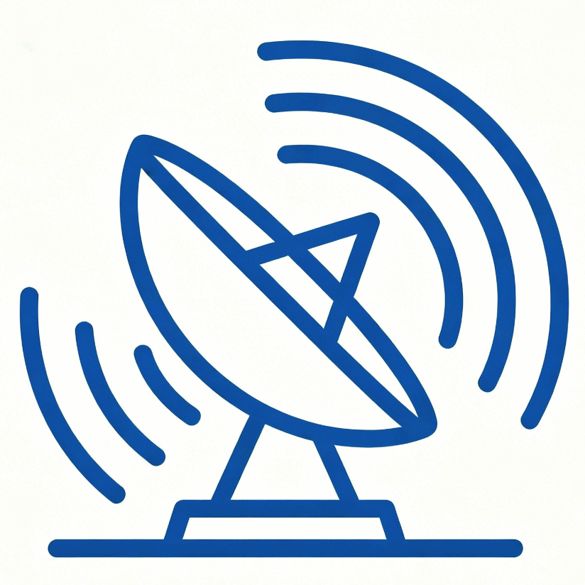
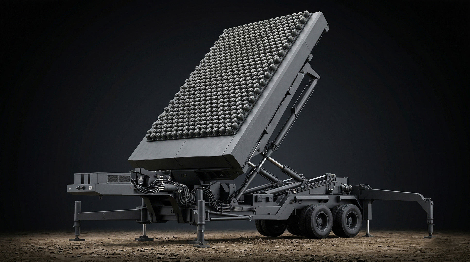
    AESA radar cooling for airborne early warning payloads, with altitude derating reviewed against the aircraft pressure profile and enclosure impedance.
  • Naval Surface Combatants

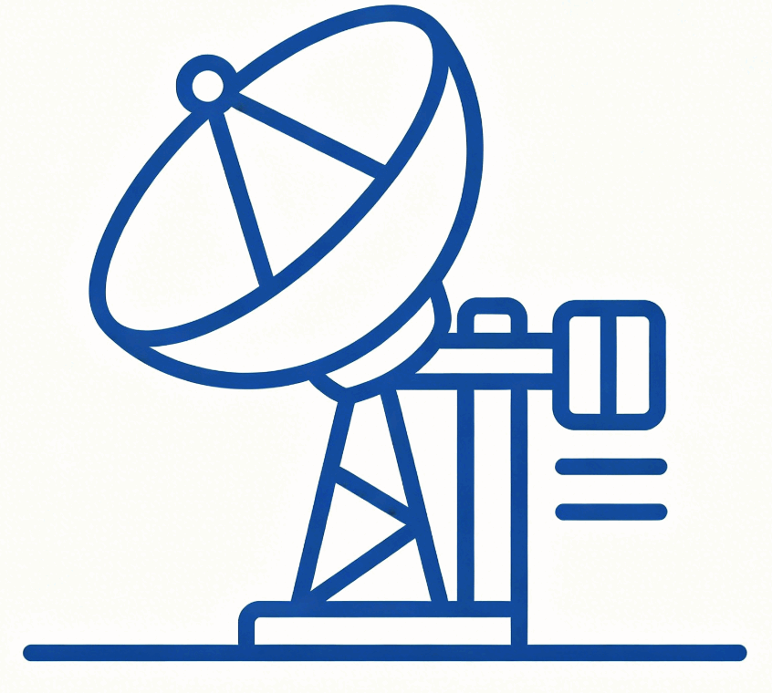
    IP67-rated fan modules and GMZ isolators protect shipborne radar against salt-fog, humidity, and wave shock.
  • Ground-Based Air Defense Radars

    Stable thermal performance from -55°C arctic to +70°C desert without external cooling infrastructure."
  • Electronic Warfare & Jamming Pods

    EMI-stealth cooling manages 500 W/cm² heat flux without interfering with SIGINT signal chains."
  • High-Power AESA T/R Module Cooling

    Liquid cold plates with micro-channel architecture dissipate 500 W/cm² heat flux from dense T/R module arrays.
  • VPX / CPCI Ruggedized Chassis

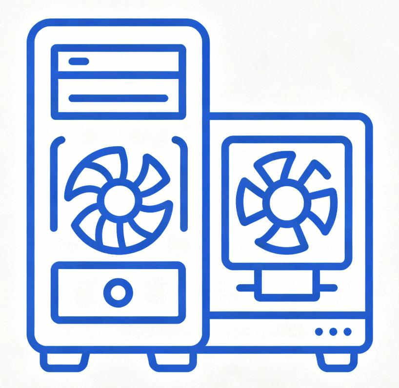
    Integrated forced-air and conduction cooling for 3U/6U VPX chassis in airborne mission computing systems.
  • High-Altitude UAV Payload Cooling

    Mixed-flow impeller concepts support radar payload thermal management where reduced air density and compact UAV envelopes limit cooling margin.
  • Directed Energy Weapons

    High-duty-cycle laser and HPM systems require continuous 500W+ heat removal from compact weapon modules.
  • Airborne SIGINT & ISR Sensor Pods

    Ultra-low EMI cooling protects wideband signal receivers from 10 kHz to 40 GHz interference in ISR pods.

Core Challenges

  • Extreme Heat Density:Modern T/R modules generate heat loads exceeding 500W per cluster in confined enclosures. Traditional cooling architectures cannot manage heat flux densities up to 500 W/cm² without compromising system reliability.
  • High-Altitude Performance Degradation:Reduced air density at altitude lowers heat-transfer capacity and can move a fan away from its intended operating point. Radar electronics should be reviewed against the platform pressure profile, enclosure impedance curve, and thermal margin before final fan selection.
  • EMI Interference with Signal Chains:Cooling fans operating near sensitive SIGINT receivers and signal processing chains risk introducing electrical noise that degrades radar performance. Any conducted or radiated emissions from cooling systems can compromise mission-critical signal integrity.
  • Shock, Vibration & Harsh Environments:Defense platforms subject cooling systems to shock loads exceeding 40G, continuous vibration, salt-fog corrosion, and temperature extremes from -55°C to +70°C. Standard commercial cooling hardware fails rapidly under these conditions.
  • SWaP Constraints:Airborne and mobile platforms impose strict Size, Weight, and Power (SWaP) budgets. Conventional cooling solutions are too heavy, too large, or consume excessive power for integration into next-generation defense systems.

How we solve it

High-Pressure Airflow for Dense Arrays:
Challenge: Dense fin-stack heat sinks in radar enclosures create extreme back-pressure that standard fans cannot overcome. Engineering Solution: Perseus engineers high-pressure tubeaxial and mixed-flow impeller geometries for elevated system impedance. Altitude derating is reviewed against the platform pressure profile and enclosure impedance curve. Performance: Air-cooled chassis solutions can support total heat dissipation targets up to 2000 W per enclosure when validated against the final architecture.

Electromagnetic RFI/EMI Stealth:
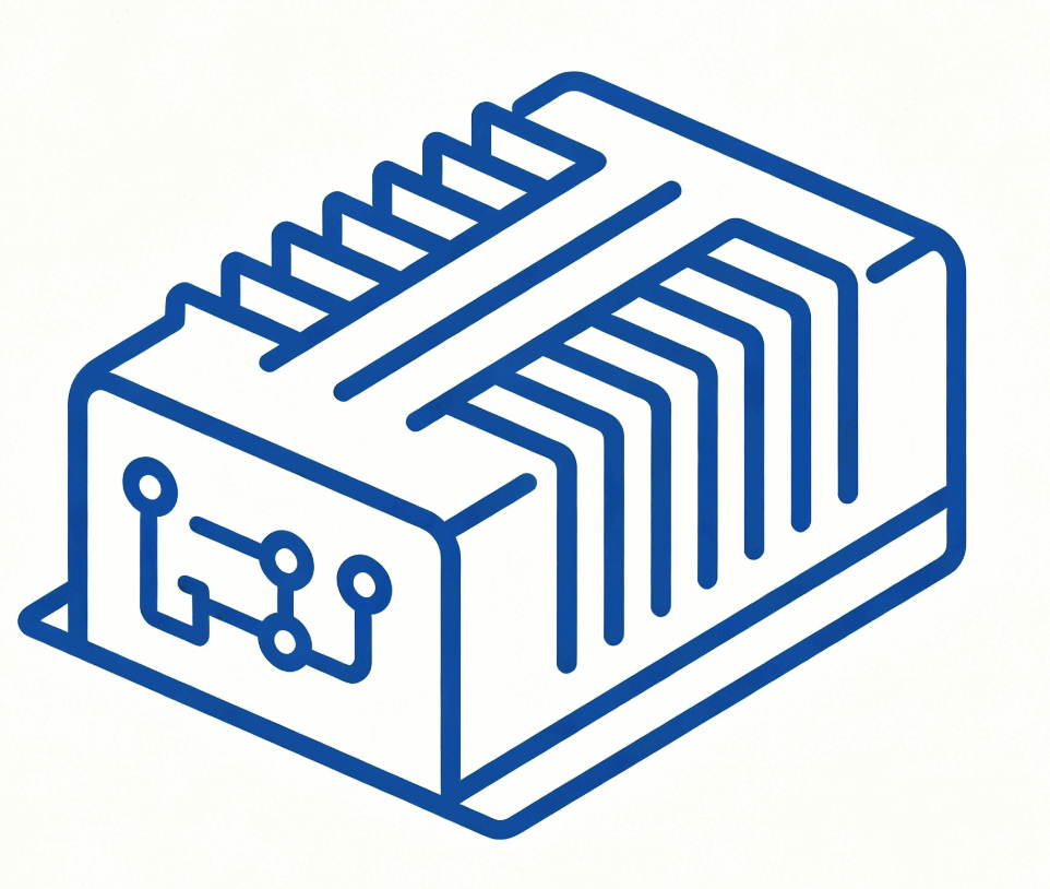
Challenge: Cooling systems must not compromise sensitive SIGINT receivers or signal processing chains. Engineering Solution: Perseus BLDC motor designs can use internal filtering, shielded cabling, conductively grounded housings, and controlled commutation behavior to reduce emission risk. Result: EMI risk is reduced through filtering, grounding, and shielding controls; final MIL-STD-461G acceptance should be verified against the platform cable layout, operating mode, and test setup.

Structural-Thermal Integration (SWaP Optimization):
Challenge: Maximize cooling performance while minimizing Size, Weight, and Power (SWaP) for airborne and mobile platforms.Engineering Solution: We integrate lightweight magnesium-aluminum alloys and carbon fiber composite chassis manufacturing. Our thermal designs combine forced-air convection with conduction pathways to reduce fan power requirements.Hardware Integration: Integrated delivery of wedge locks, injectors, and ruggedized enclosures for VPX, CPCI, and ASAAC architectures.

Cooling MethodHeat Flux CapacityWeight PenaltyEMI RiskBest For
Air-Cooled (Forced Convection)Up to 200 W/cm²LowLow (with proper shielding)Standard radar arrays, VPX chassis
Liquid-Cooled (Flow-Through)Up to 500 W/cm²MediumNoneHigh-power T/R modules, optical modules
Conduction-CooledUp to 100 W/cm²HighNoneSpace-constrained pods, sealed enclosures

Frequently AskedQuestions (FAQ)

  • How should EMC be reviewed for fans near radar, EW, or communication receivers?
    A: Fans near radar, EW, SIGINT, datalink, or communication receivers should be reviewed for both conducted and radiated emissions. CE102 is commonly used to evaluate conducted emissions on power leads from 10 kHz to 10 MHz, while RE102 evaluates radiated electric-field emissions from the unit and cables across the range defined by the platform test plan. Practical risk reduction comes from filtering, cable routing, shield termination, grounding strategy, and testing the fan in the same operating mode used by the host equipment. 
  • Why do high-impedance ducts or fin stacks need static-pressure-focused fan selection?
    A: Free-air CFM is measured at zero static pressure and is not the airflow delivered inside a dense enclosure. Heat sinks, filters, louvers, long ducts, and tight VPX/CPCI card cages create system resistance. The real airflow is the intersection of the fan P-Q curve and the system impedance curve. Centrifugal fans are often a better fit for high-impedance paths because they maintain pressure through narrow or redirected airflow channels, while axial fans are better for lower-resistance, direct-through cooling. 
  • What motor commutation and PWM frequencies matter for EMI troubleshooting?
    A: Two frequency families matter. Motor commutation frequency depends on pole count and RPM; for example, a 4-pole motor at 6,000 RPM produces a 400 Hz commutation frequency. PWM gate-drive or speed-control switching may sit much higher; selected Perseus BLDC fans use a 15.625 kHz internal switching frequency during startup or speed-controlled operation. EMI troubleshooting should look at both the low-frequency commutation components and the higher-frequency switching components on the power and signal harness. 
  • How do I estimate required airflow from heat load before pressure drop is known?
    A: Start with heat load, allowable temperature rise, and air properties. A practical first-pass estimate is airflow equals heat load divided by air density, specific heat, and allowed temperature rise. Using 1.225 kg/m3 air density and 1,004 J/kg-K specific heat, a 400 W load with a 10°C rise needs about 117 m3/h before pressure-loss margin. If the enclosure pressure drop is unknown, select an initial fan target around 1.3 to 2.0 times the calculated airflow, then verify the operating point with P-Q data. 
  • What test documentation should I request before qualification or RFQ?
    A: For a serious RFQ, request the P-Q curve, outline drawing, electrical interface definition, connector or lead specification, inrush-current data, PWM/FG/RD logic, acoustic data, bearing-life basis, and environmental test references. For defense and aerospace programs, also request the applicable MIL-STD-810H method matrix, CE102/RE102 pre-screening data when EMC risk exists, and the power-quality reference such as MIL-STD-704 or MIL-STD-1275. The best supplier response ties each document to your platform test plan rather than sending a generic catalog page.