


Heavy-Duty High-Capacity DC Fans for Defense Applications
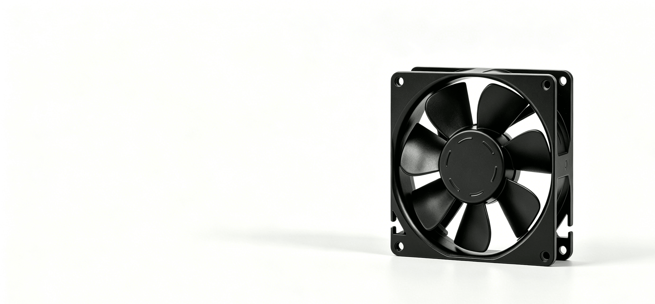
Ruggedized, large-scale thermal management for airborne radar bays, avionics enclosures, and military power supply modules operating in sustained harsh environments.
Large military power systems don't fail from insufficient cooling capacity on paper — they fail because the fan that looked adequate in a datasheet couldn't sustain that performance at 55°C ambient, after 40G shock, with a partially clogged filter and 18 months of salt-fog exposure.

Perseus Large DC Fans are built for that reality. Oversized blade geometries, die-cast aluminum housings, and precision dual ball bearing systems aren't marketing features — they're the difference between a fan that meets spec on delivery and one that's still running at the end of a deployment cycle. For defense applications where fan replacement requires depot-level maintenance, MTBF isn't a footnote. It's a program requirement.
Core Technical Features
High-Capacity Airflow Output:
Oversized blade geometries move up to 892.65 CFM — enough to manage the thermal load of large military power conversion systems and ground radar transmission equipment where smaller fans cannot shift sufficient air mass regardless of how many are installed.
Depot-Level Structural Durability:
Die-cast aluminum housings resist deformation under shock loads that crack polymer frames. Dual ball bearing systems deliver extended MTBF at continuous high-temperature operation — validated across avionics bay installations where unscheduled fan replacement means taking the platform offline.
Real-Time Health Telemetry:
Built-in tachometer feedback, PWM speed control, and fault alarm outputs give system integrators real-time fan health data. In practice, this means catching bearing degradation before it becomes a mission abort — not after.
MIL-STD-810H Qualification Planning:
Designed for model-specific extreme-temperature review, high mechanical shock, rain ingress, and acidic atmospheres. The Archpro series adds 192-hour acidic salt spray resistance for the most corrosive maritime and industrial defense environments.
Typical Applications
-
![]()
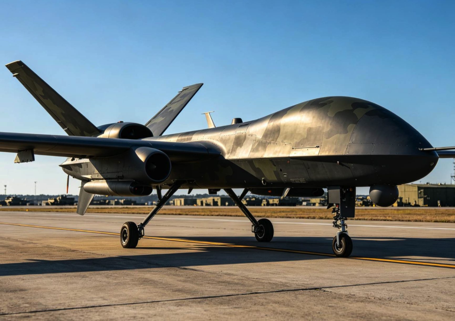
Large avionics bays on maritime patrol aircraft and transport platforms house multiple high-power electronics assemblies generating sustained heat loads. The Megapro and Hyperpro series deliver the airflow volume needed to maintain bay temperatures within operating limits across long-duration missions.
Avionics Bay Cooling Systems
-
![]()
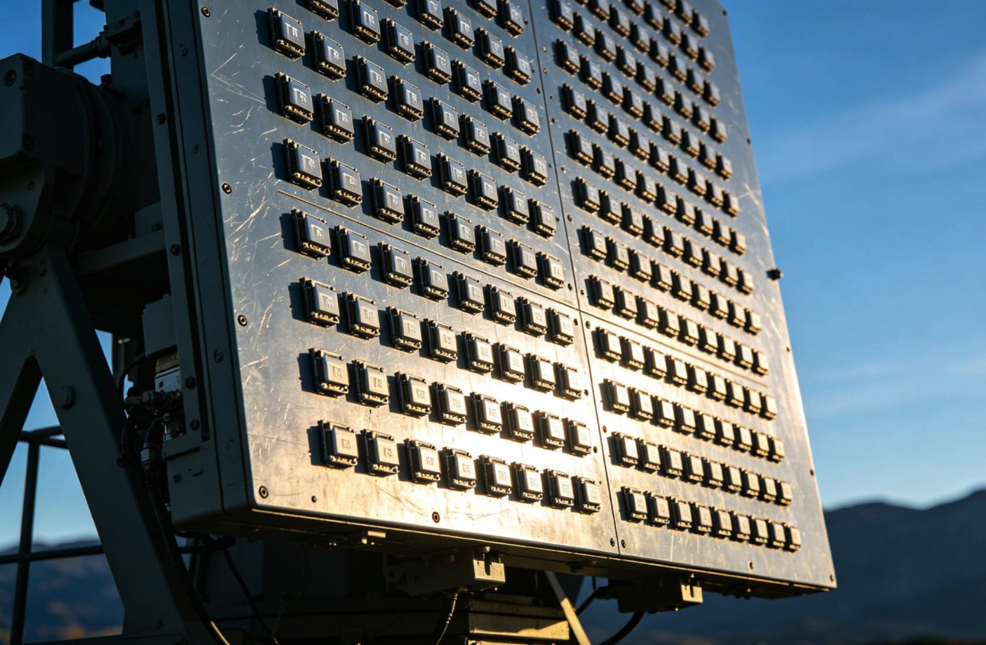
High-power radar transmitters generate continuous heat loads in fixed and mobile ground installations. The Archpro series handles the sustained airflow demands of transmission equipment operating in desert environments where ambient temperatures regularly exceed +55°C.
Ground-Based Radar Transmission Systems
-
![]()
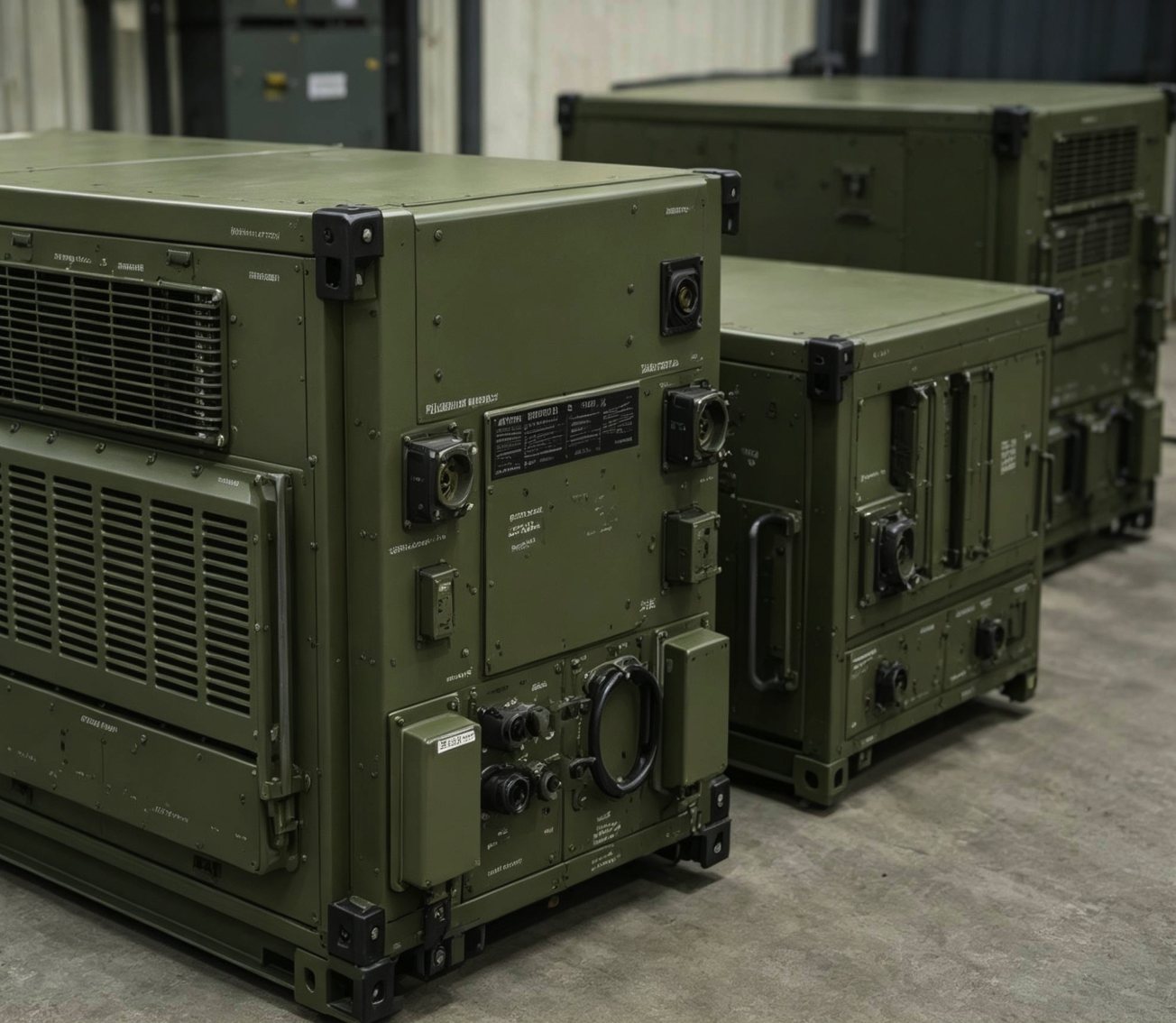
Power conversion modules for vehicle-mounted and shelter-based systems require reliable cooling under the random vibration profiles of tracked and wheeled vehicles. The Megapro's tracked vehicle vibration validation directly addresses this failure mode.
Large Military Power Supply Modules
-
![]()
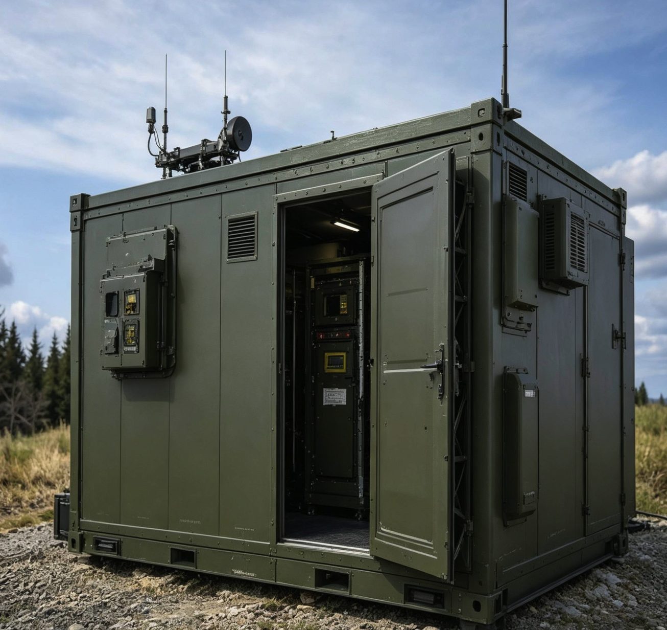
Forward-deployed command and communications shelters need ventilation systems that set up fast, run continuously, and survive transport shock. The large-frame series provides the airflow capacity to maintain shelter temperatures without reliance on external HVAC infrastructure.
Mobile Electronic Shelter Ventilation
Series Selection Guide
| Series | Frame Size | Max Airflow (CFM) | Power Range (W) |
|---|---|---|---|
| Megapro | 90–100mm | 301.00 | 110–1750g |
| Hyperpro | 120mm | 342.00 | 165–505g |
| Archpro | >120mm | 892.65 | 420–4500g |
Model Reference
Below are representative models — one per series — illustrating key performance parameters and environmental adaptabilities.
Each PQ curve shows measured static pressure vs. airflow at rated voltage.
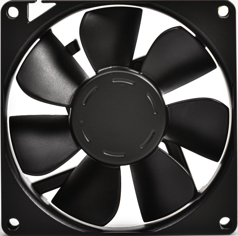
Megapro PCG85FZW36-25G-AG
92mm x 92mm x 25.4mm Frame
12V DC Platform

Core Electrical & Performance Parameters
| Parameter | Specification |
|---|---|
| Rated Voltage | 12V DC |
| Voltage Range | 10-13.5V DC |
| Operating Current (Free Air) | <=0.66A |
| Inrush Current | <=1.65A |
| Rated Power (Free Air) | <=7.92W |
| Rated Rotational Speed | 6,500 RPM +/-10% |
| Max Airflow | 78.89 CFM / 133.95 m3/h |
| Max Static Pressure | 19.14 mmH2O / 187.57 Pa |
| Acoustic Noise | <=57.5 dB(A) |
| Speed Control Mode | PWM |
| Output Signal | FG (Frequency Generator) |
| Rotation Direction | Counterclockwise, viewed from impeller side |
Mechanical & Environmental Parameters
| Parameter | Specification |
|---|---|
| Frame Size | 92mm x 92mm x 25.4mm |
| Frame / Impeller Material | Aluminum alloy or PPO configuration; final material by selected variant |
| Bearing Type | Dual ball bearing |
| Weight | 160g |
| Protection Rating | IP68 configuration option |
| Lead Interface | AWG24 power, FG, and PWM leads; >=300mm lead length |
| Insulation Resistance | >=10MOhm at 500V DC, frame-to-lead |
| High-Temperature Life | >=1,000h at +75C operating condition |
| Operating Temperature Range | -45C to +75C |
| Storage Temperature Range | -55C to +75C |
| Salt Fog Exposure | 96h neutral salt spray profile |
| Humidity Exposure | 95% +/-5% RH, 10 cycles of 24h |
| Rain Exposure | Rain and blowing-rain exposure profile |
| Sand & Dust Exposure | Dust and sand blowing exposure profile |
| Mechanical Shock | 40g peak, 15-23ms functional shock profile |
| Acceleration | 13.5g overload profile |
| Temperature Shock | -50C to +70C, 2h dwell, 3 cycles |
| EMC Planning Reference | MIL-STD-461G CE102 / RE102 planning reference; final limits by platform test plan |
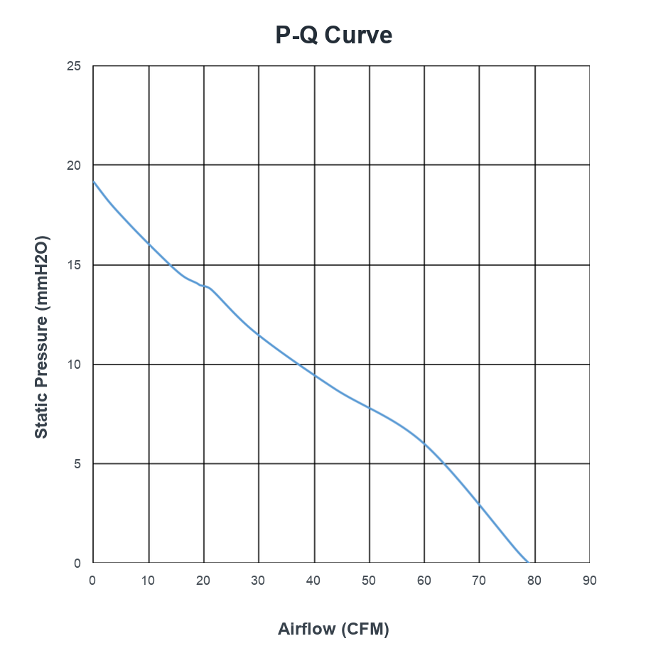
P-Q Curve — PCG85FZW36-25G-AG @ 12V DC
At nominal input conditions, this reference curve maps static pressure from 0-19.14 mmH2O against airflow from 0-78.89 CFM. Use it for first-pass operating-point review; full-resolution P-Q curves, CAD files, and product-specific datasheets are available for qualified RFQ review.
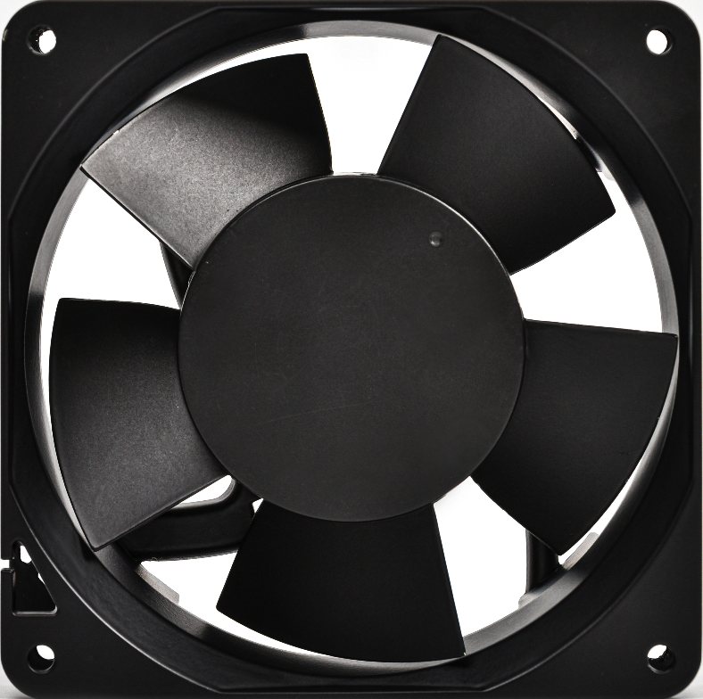
Hyperpro PCG112FZW53-38G-AC
119.2mm x 119.2mm x 38mm Frame
28V DC Platform
Core Electrical & Performance Parameters
| Parameter | Specification |
|---|---|
| Rated Voltage | 28V DC |
| Voltage Range | 18-32V DC |
| Operating Current (Free Air) | 0.25A |
| Peak / Starting Current | <=0.62A |
| Rated Power (Free Air) | 7.00W |
| Rated Rotational Speed | 3,300 RPM +/-10% |
| Max Airflow | 125.3 CFM / 212.7 m3/h |
| Max Static Pressure | 9.5 mmH2O / 93.1 Pa |
| Acoustic Noise | 54.7 dB(A), Max 57.7 dB(A) |
| Speed Control Mode | PWM |
| Output Signal | RD (Rotation Detector) |
| Rotation Direction | Clockwise, viewed from impeller side |
Mechanical & Environmental Parameters
| Parameter | Specification |
|---|---|
| Frame Size | 119.2mm x 119.2mm x 38mm |
| Frame / Impeller Material | Aluminum alloy or PPO configuration; final material by selected variant |
| Bearing Type | Dual ball bearing |
| Weight | 447g |
| Protection Rating | IP68 configuration option |
| Lead Interface | AWG24 power, RD, and PWM leads |
| L10 Life | >=50,000h at 40C, 15-65% RH |
| Operating Temperature Range | -55C to +85C |
| Storage Temperature Range | -55C to +85C |
| Salt Fog Exposure | 192h acidic salt spray profile |
| Humidity Exposure | 95% +/-5% RH, 10 cycles of 24h |
| Rain Exposure | Intensified rain exposure, 40min per side |
| Mechanical Shock | 30g peak, 11ms sawtooth, 18 total shocks |
| Acceleration | 9g performance / 13.5g structural profile |
| Temperature Shock | -60C to +95C, transfer time <1min, 3 cycles |
| Power Transient Planning | MIL-STD-704 planning reference available by program review |
| EMC Planning Reference | MIL-STD-461G CE102 / RE102 planning reference; final limits by platform test plan |
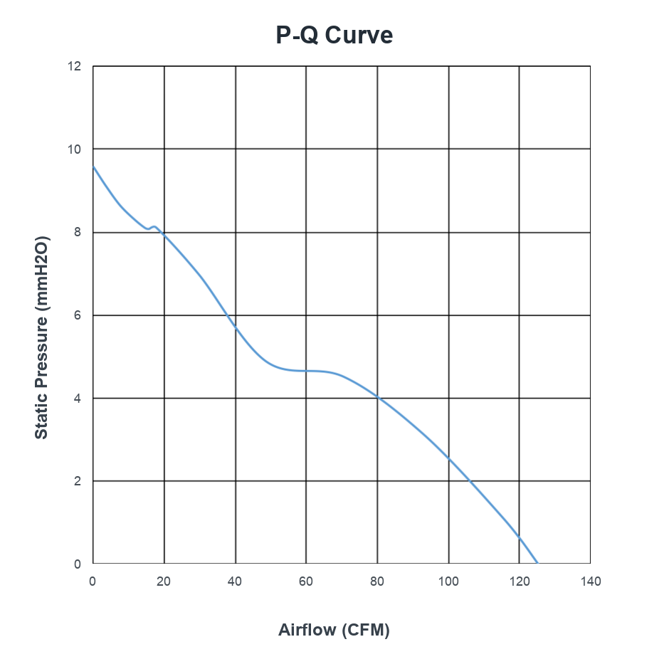
P-Q Curve — PCG112FZW53-38G-AC @ 28V DC
At nominal input conditions, this reference curve maps static pressure from 0-9.5 mmH2O against airflow from 0-125.3 CFM. Use it for first-pass operating-point review; full-resolution P-Q curves, CAD files, and product-specific datasheets are available for qualified RFQ review.
Archpro PCG148FZW46-51GXBH
Dia. 171.5mm x 50.8mm Frame
24V DC Platform
Core Electrical & Performance Parameters
| Parameter | Specification |
|---|---|
| Rated Voltage | 24V DC |
| Voltage Range | 18-26.5V DC |
| Operating Current (Free Air) | <=2.50A |
| Rated Power (Free Air) | <=60.00W |
| Rated Rotational Speed | 6,500 RPM +/-10% |
| Max Airflow | 370.93 CFM / 629.84 m3/h |
| Max Static Pressure | 60.52 mmH2O / 593.09 Pa |
| Acoustic Noise | 67.9 dB(A), Max 70.9 dB(A) |
| Speed Control Mode | PWM |
| Output Signal | FG (Frequency Generator) |
| Rotation Direction | Counterclockwise, viewed from impeller side |
Mechanical & Environmental Parameters
| Parameter | Specification |
|---|---|
| Frame Size | Dia. 171.5mm x 50.8mm |
| Frame / Impeller Material | Aluminum alloy or PBT configuration; final material by selected variant |
| Bearing Type | Dual ball bearing |
| Weight | 1200g |
| Protection Rating | IP68 configuration option |
| Lead Interface | AWG20 power leads, AWG24 FG/PWM leads; >300mm lead length |
| Insulation Resistance | >=10MOhm at 500V DC, frame-to-lead |
| Dielectric Withstand | <1mA at 500V DC, frame-to-lead |
| L10 Life | >=50,000h at 40C, 15-65% RH |
| Operating Temperature Range | -55C to +85C |
| Storage Temperature Range | -55C to +85C |
| Salt Fog Exposure | 96h neutral salt spray profile |
| Humidity Exposure | 95% +/-5% RH, 10 cycles of 24h |
| Rain Exposure | Intensified rain exposure, 40min per side |
| Sand & Dust Exposure | Dust and sand blowing exposure profile |
| Mechanical Shock | 30g peak, 11ms sawtooth, 18 total shocks |
| Acceleration | 9g performance / 13.5g structural profile |
| Temperature Shock | -55C to +85C, transfer time <1min, 3 cycles |
| EMC Planning Reference | MIL-STD-461G CE102 / RE102 planning reference; final limits by platform test plan |
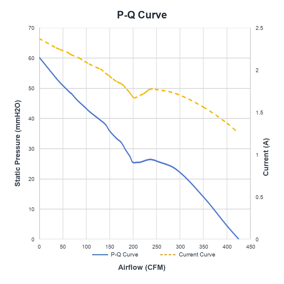
P-Q Curve — PCG148FZW46-51GXBH @ 24V DC
At nominal input conditions, this reference curve maps static pressure from 0-60.52 mmH2O against airflow from 0-370.93 CFM. Use it for first-pass operating-point review; full-resolution P-Q curves, CAD files, and product-specific datasheets are available for qualified RFQ review.
Full-resolution PQ curves, CAD models (STEP/IGES), and complete datasheets for all models are available upon RFQ.


This reference covers one model in one frame size. The full Megapro / Hyperpro / Archpro library includes 50+ validated configurations across 90mm–171.5mm frames, with custom voltage, airflow, and connector options.