


Integrated Thermal Management Systems for Defense Electronics
Air-Cooled Chassis, Liquid Cold Plates, and Phase-Change Thermal Hardware
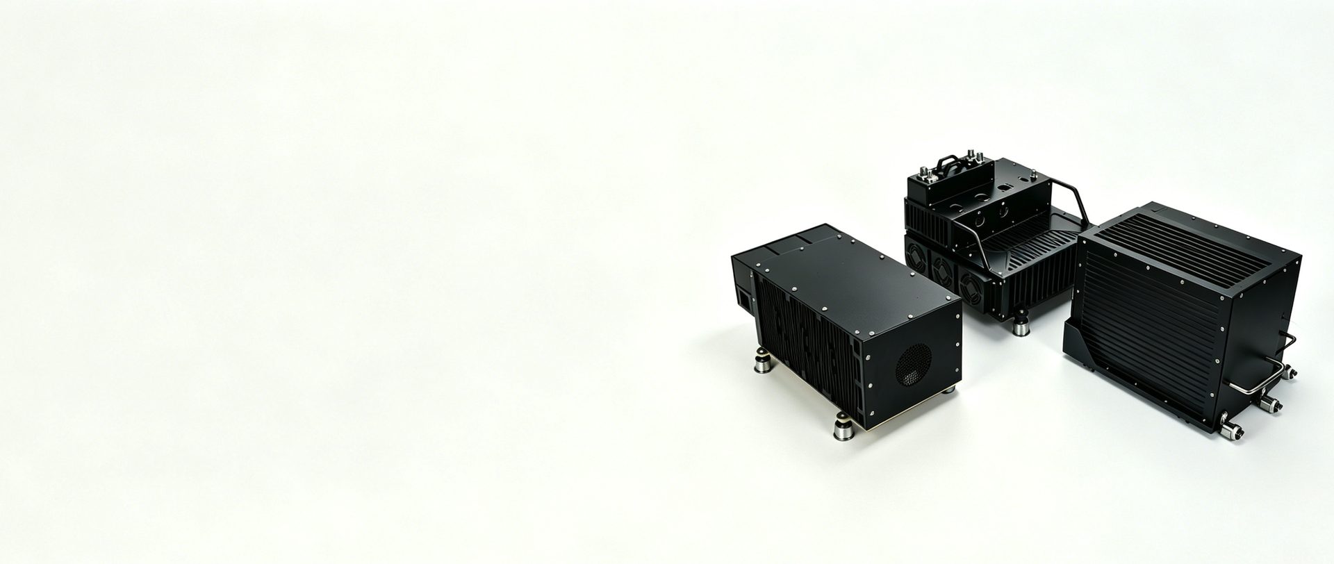
Perseus designs integrated thermal management systems for defense electronics operating in airborne, naval, ground, and high-reliability environments. Architecture options include fan-assisted air-cooled enclosures up to 2,000 W per chassis, liquid-cooled systems managing heat flux density up to 200 W/cm² at the module interface, and passive thermal hardware such as heat pipes and phase-change cold plates for transient heat loads.
Core Technical Features
Integrated Fan and Chassis Ecosystem:
Perseus can coordinate airflow source, enclosure architecture, and system impedance to reduce interface risk in thermal design reviews.
High-Capacity Heat Dissipation:
Air-cooled enclosures can support up to 2,000 W per chassis, while liquid-cooled architectures can support up to 200 W/cm² at the module interface by configuration.
Liquid Cold Plate Integrity:
Vacuum-brazed and friction-stir-welded cold plate concepts can be reviewed for PAO, EGW, or Jet-A compatible cooling loops.
Passive and Transient Thermal Control:
Heat pipe assemblies and phase-change material cold plates help manage short-duration thermal spikes when steady-state airflow alone is not sufficient.
Typical Applications
-
![]()
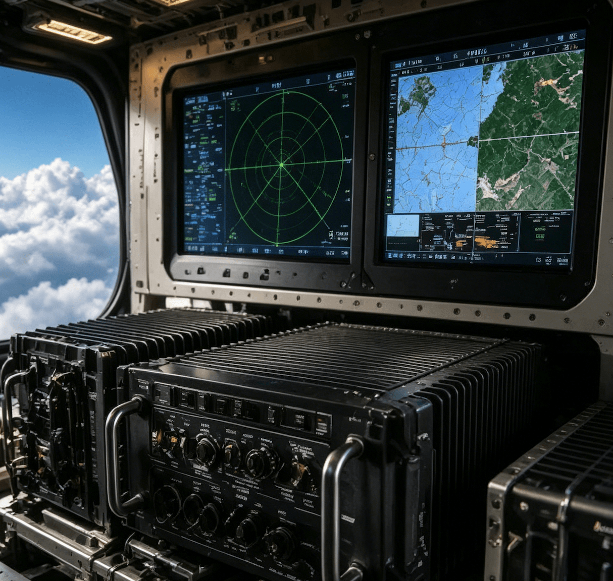
Supports fan-assisted or conduction-cooled chassis for avionics, radar processors, and mission computers where SWaP and qualification schedules must be balanced.
Airborne Mission Computers and Radar Systems
-
![]()
Applies to naval consoles, radar cabinets, and communication electronics that require controlled cooling and corrosion-aware mechanical design.
Shipboard Electronics Cabinets
-
![]()
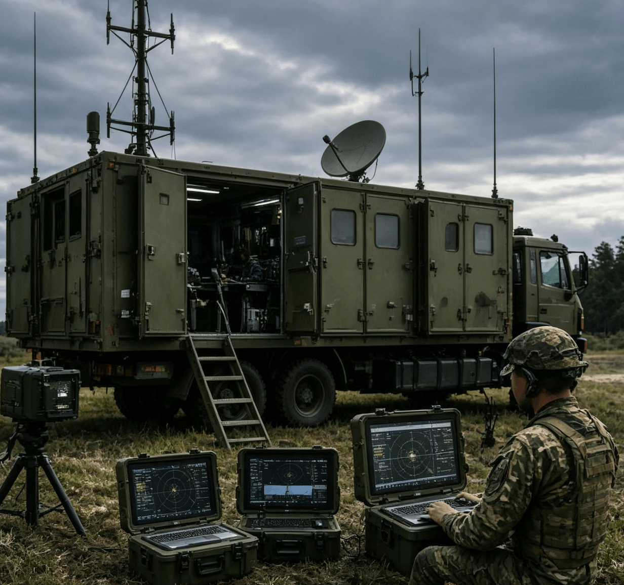
Supports rugged shelter and vehicle electronics where enclosure impedance, dust exposure, and maintainability affect the thermal architecture.
Ground Mobile Command and Control
-
![]()
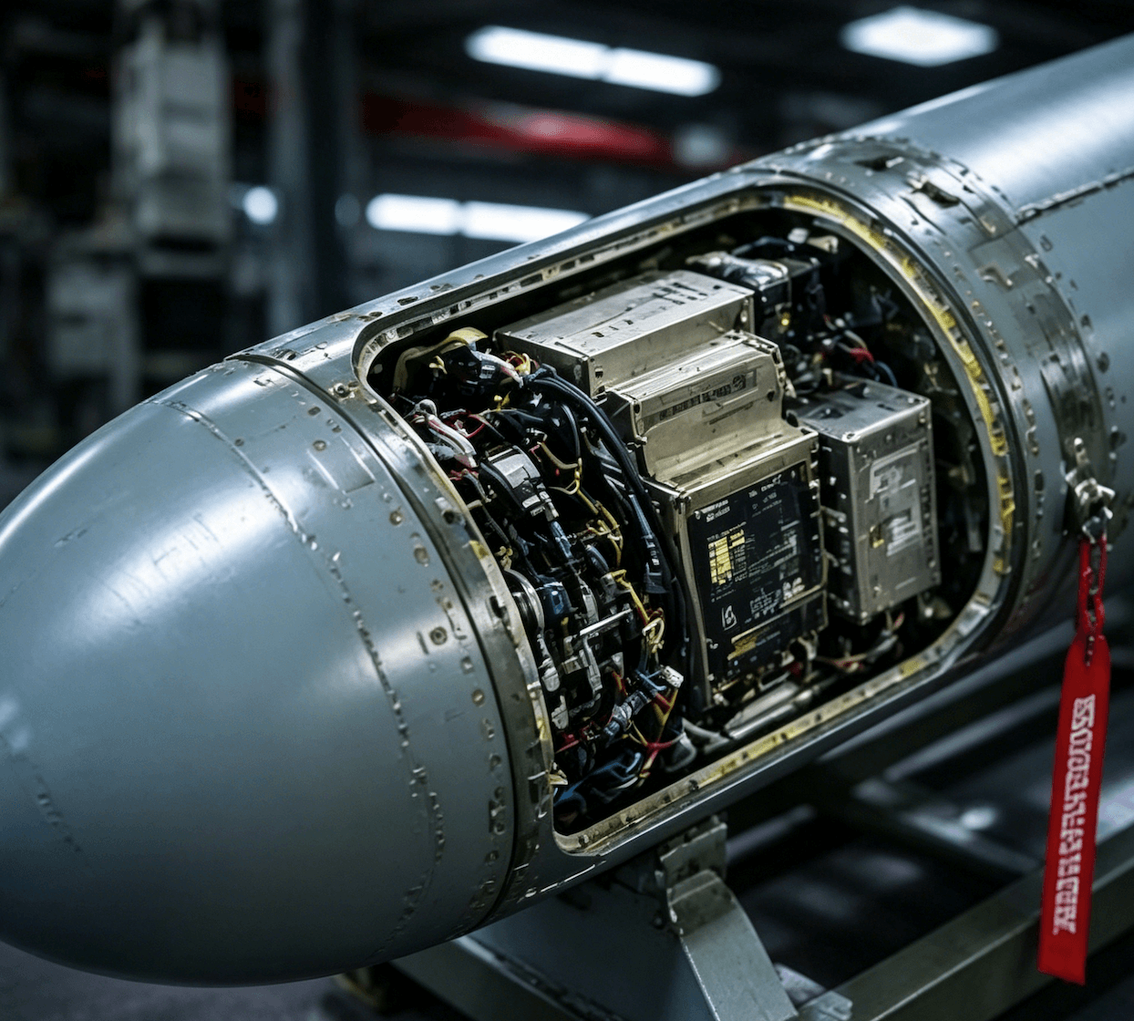
Uses conduction paths, cold plates, heat pipes, or phase-change hardware where airflow space is limited and transient heat loads are high.
Compact Payload and Guidance Electronics

Series Selection Guide
Series 1: Air-Cooled Chassis
| Configuration | Slot Count | Module Standard | Thermal Capacity | Cooling Method | Weight | Dimensions | Operating Temp |
|---|---|---|---|---|---|---|---|
| 1/2 ATR Air-Cooled | 3U modules | VPX / CPCI / ASAAC | Up to 800 W | Aerospace fans | ~13.5 kg | 315 x 194 x 124 mm | By configuration |
| 1 ATR Air-Cooled | 3U modules | VPX / CPCI / ASAAC | Up to 2,000 W | Aerospace fans | ~27.5 kg | 315 x 194 x 256 mm | By configuration |
| 4 MCU Air-Cooled | 3U / 6U modules | VPX / custom | Up to 1,000 W | Centrifugal fans | Custom | Custom | By configuration |
| VPX Air-Cooled | 8 x 6U VPX | VITA 46 / 48 | Up to 1,000 W | Axial fans | Custom | Custom | By configuration |
Series 2: Conduction-Cooled Chassis
| Configuration | Slot Count | Module Standard | Thermal Capacity | Heat Sink Type | Weight | Dimensions | Operating Temp |
|---|---|---|---|---|---|---|---|
| 1/2 ATR Conduction | 3U modules | VPX / CPCI / ASAAC | Up to 800 W | Machined aluminum | ~13.5 kg | 315 x 194 x 124 mm | -55°C to +85°C |
| 4 MCU Conduction | 3U / 6U modules | VPX / custom | Custom | Finned heat sink | Custom | Custom | -55°C to +85°C |
| Custom ATR Conduction | Variable | ASAAC / custom | Up to 800 W | Cold plate / conduction path | Custom | Custom | -55°C to +85°C |
Series 3: Liquid-Cooled Chassis
| Configuration | Slot Count | Module Standard | Heat Flux Density | Cold Plate Type | Weight | Dimensions | Operating Temp |
|---|---|---|---|---|---|---|---|
| 4U Liquid-Cooled Rack | VPX modules | VITA 48 | 50-200 W/cm² | Blind-mate connectors | Custom | 4U rack height | By configuration |
| Airborne Liquid-Cooled | Variable | VPX / custom | 50-200 W/cm² | Serpentine flow path | Custom | Custom | By configuration |
| RF Liquid-Cooled | High-power RF | Custom | Up to 200 W/cm² | Microchannel option | Custom | Custom | By configuration |
Thermal Management Modules Overview
Perseus thermal management modules combine cooling fans, chassis architecture, conduction paths, liquid cold plates, heat pipes, and phase-change hardware into application-specific thermal solutions for defense electronics.
Architecture selection should be based on heat load, module standard, enclosure impedance, fluid compatibility, shock and vibration exposure, EMC requirements, and maintenance access. Qualification planning can reference MIL-STD-810H Method 514.8 / 516.8 and MIL-STD-461G CE102 / RE102 when those requirements are included in the platform test plan.
- Thermal target
Share heat load, hot spots, airflow path, and allowable pressure drop.- Mechanical interface
Provide module standard, slot count, envelope, mass target, and mounting constraints.- Qualification plan
Define vibration, shock, EMC, ingress protection, and acceptance criteria by platform.