Home
Technical Resources
Technical Notes

Low-Noise Military Axial Fans: Acoustic Signature Reduction in Tactical Cooling Systems

May 14, 2026 Author:High-Performance Fan Engineering Team

Overview

This technical note documents the aeroacoustic design decisions in Perseus PFM-series axial fans—covering trailing-edge geometry, tip-vortex suppression, and the relationship between reduced rotational speed and bearing longevity. It is intended to support acoustic engineers and systems integrators evaluating cooling components for noise-sensitive tactical platforms.


The Actual Problem: Where Fan Acoustic Noise Originates

Fan-generated acoustic noise in axial cooling fans has two distinct physical origins that require separate design responses:

Broadband noise is generated continuously as airflow separates from the blade trailing edge, shedding turbulent vortices into the downstream wake. Its intensity scales with the sixth power of blade tip speed—halving tip speed reduces broadband noise by approximately 18 dB, which is why speed reduction is the single most effective acoustic mitigation strategy.

Tonal noise occurs at the blade pass frequency (BPF) and its harmonics:


BPF=RPM×Nblades


Tonal components are perceptually more intrusive than broadband noise at equivalent SPL and are more easily detected by passive acoustic sensors. They originate primarily from two sources: periodic pressure fluctuations as each blade passes through non-uniform inlet flow, and tip-vortex shedding at the blade-to-shroud clearance.

Standard fan designs address neither mechanism at the blade geometry level. Perseus addresses both.


Trailing-Edge Geometry: Vortex Filament Fragmentation

The Mechanism

A straight trailing edge sheds a coherent, large-scale vortex street as airflow separates from the blade surface. This coherent shedding is acoustically efficient—it radiates broadband noise effectively because the vortex structures are large relative to the acoustic wavelengths of interest (roughly 1 kHz–8 kHz for fan noise in tactical enclosures).

Perseus Implementation

Perseus PFM-series blades incorporate a serrated trailing-edge profile with defined tooth geometry (pitch and amplitude optimized per blade chord length). The serrations interrupt the spanwise coherence of vortex shedding, breaking large-scale vortex structures into smaller, less energetic filaments before they detach from the blade surface.

The acoustic effect is a reduction in broadband SPL concentrated in the 1 kHz–4 kHz octave bands—the frequency range where human hearing is most sensitive and where many tactical acoustic detection systems operate.

Perseus validates trailing-edge acoustic performance under ISO 3744 (sound power level, hemispherical measurement surface, semi-anechoic environment). Test conditions are standardized at:

Inlet flow: uniform, no upstream obstructions within 3× fan diameter

Measurement distance: 1 m from fan centerline

Ambient background SPL: ≥ 6 dB below fan SPL at each measurement point

Transparency note: ISO 3744 measures sound power level (L_W) under controlled laboratory conditions. Installed SPL in a specific enclosure depends on enclosure geometry, airflow path restrictions, and mounting surface acoustic absorption—variables outside the fan's design envelope. Perseus can provide L_W data; enclosure-level SPL prediction requires system-level acoustic modeling.


Tip-Vortex Suppression: Eliminating the Primary Tonal Source

The Mechanism

At the blade tip, a pressure differential exists between the pressure side (high pressure) and suction side (low pressure) of the blade. This differential drives a leakage flow around the tip from pressure side to suction side, rolling up into a concentrated tip vortex. As this vortex sheds periodically with each blade pass, it generates the dominant tonal component at BPF and its harmonics.

Tip clearance is a critical parameter: tighter clearance reduces leakage flow but increases the risk of blade-to-shroud contact under thermal expansion or vibration-induced deflection. Standard designs use conservative (large) tip clearances to avoid contact, which worsens tonal noise.

Perseus Implementation

Perseus PFM-series blades incorporate winglet structures at the blade tip—a turned geometry that redirects the tip leakage flow back toward the pressure side before it can roll up into a coherent vortex. This reduces tip-vortex strength without requiring tighter physical clearance.

The practical result is attenuation of BPF tonal components, which Perseus measures as part of the standard acoustic characterization under IEC 60034-9 (noise limits for rotating electrical machines). IEC 60034-9 compliance is verified at rated voltage and rated airflow resistance—not at free-delivery (zero static pressure) conditions, which would understate operational noise levels.

Boundary condition: Winglet effectiveness is sensitive to tip clearance tolerance. Perseus specifies a maximum tip clearance of 0.5 mm for PFM-series fans. Installations that cannot maintain this tolerance due to thermal expansion or mounting compliance should be reviewed with the Perseus applications team before final selection.


Speed Reduction as the Primary Acoustic Strategy

The serrated trailing edge and winglet geometry are enabling technologies, not the primary noise reduction mechanism. Their primary function is to allow the fan to achieve required airflow performance at lower rotational speed than a conventional blade geometry of equivalent diameter.

Lower rotational speed reduces acoustic output through two independent physical mechanisms:

Noise TypeSpeed Scaling LawPractical Implication
Broadband (trailing edge)SPL ∝ U⁶ (tip speed)−18 dB per halving of tip speed
Tonal (BPF)Frequency ∝ RPMLower RPM shifts BPF below sensitive detection bands

This speed reduction also directly affects mechanical reliability. Perseus bearing life follows the standard L₁₀ relationship:

L10(1N)3

where N is rotational speed. A 20% reduction in operating RPM extends calculated L₁₀ bearing life by approximately 95%—nearly doubling it—independent of any other design change.

Perseus validates structural integrity of the blade geometry under maximum aerodynamic load conditions using finite element analysis (FEA), with load cases defined at:

Maximum rated airflow resistance (highest blade bending moment)

Maximum operating temperature (+85°C for standard PFM-series)

Combined aerodynamic and inertial loading at rated RPM

FEA results establish the minimum safety factor on blade root stress. Perseus can provide FEA summary data upon request for structural integration review.


Application Scenarios: Where Acoustic Design Decisions Matter

1 Mobile Command and Intelligence Nodes

Ground-based mobile command platforms operate in environments where acoustic signature management is an operational requirement, not a comfort preference. Cooling fan noise that exceeds ambient levels can compromise position concealment in forward-deployed configurations.

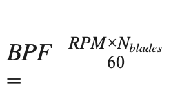
Relevant Perseus feature: The combination of serrated trailing edge and reduced operating RPM targets the 1 kHz–4 kHz band where passive acoustic detection is most sensitive. Tonal suppression via winglet geometry eliminates the periodic BPF signature that is most easily distinguished from ambient broadband noise.

Boundary condition: Enclosure-level acoustic signature depends on airflow path design, panel transmission loss, and generator noise—all system-level variables. Fan-level L_W data is a necessary but not sufficient input to enclosure acoustic modeling.

2 Unmanned Aerial Vehicles (UAV) and Loitering Munitions

Small UAV platforms face simultaneous acoustic and SWaP-C constraints. Acoustic noise from avionics bay cooling fans can interfere with onboard acoustic sensors (microphones, sonar altimeters) and contribute to the platform's acoustic detectability.

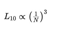
Relevant Perseus feature: Tonal noise suppression is particularly relevant for UAV applications, where BPF harmonics can fall within the passband of onboard acoustic sensors. Reduced operating RPM also lowers motor power consumption, directly improving endurance.

Boundary condition: UAV airframe vibration isolation between the fan mounting structure and the acoustic sensor mounting structure is a system integration variable. Perseus can provide vibration force transmissibility data to support isolation design.

3 Submarine and Underwater Vehicle Electronics Bays

Submarine platforms operate under strict radiated noise requirements across acoustic, magnetic, and electrical domains. Cooling system acoustic emissions that transmit through the hull structure contribute to the platform's underwater acoustic signature.

Relevant Perseus feature: Tonal noise suppression is the primary relevant feature for submarine applications, as tonal components transmit through structure more efficiently than broadband noise and are more easily detected by passive sonar. Single-point grounding (from PFM-series EMC architecture) also reduces magnetic signature contribution from motor current harmonics.

Boundary condition: Structure-borne noise transmission from fan to hull depends on mounting isolation design and hull structural dynamics—system-level variables that require platform-specific analysis.


What This Architecture Does Not Replace

Perseus PFM-series acoustic design reduces the fan assembly's contribution to system acoustic signature. It does not substitute for:

  Enclosure acoustic treatment: Panel transmission loss, internal absorption lining, and airflow path geometry determine how fan-generated noise couples to the external environment.

  Vibration isolation mounting: Fan vibration transmitted through rigid mounting hardware bypasses airborne acoustic suppression entirely. Perseus recommends elastomeric isolation mounts for all noise-sensitive installations.

  System-level acoustic modeling: Enclosure-level SPL prediction requires combining fan L_W data with enclosure transfer functions—a system integration task outside the fan's design envelope.


Documentation Available to Support Acoustic Integration

Perseus can provide the following upon request:


DocumentContents
ISO 3744 acoustic test reportSound power level (L_W) vs. airflow resistance, per octave band
IEC 60034-9 compliance dataBPF tonal levels at rated operating conditions
Airflow performance curveStatic pressure vs. flow rate at rated voltage
FEA structural summaryBlade root safety factor at maximum aerodynamic load
Vibration force transmissibilityBearing housing vibration force vs. frequency at rated RPM
L₁₀ bearing life calculationPer ISO 281, at rated speed and operating temperature

This document reflects Perseus internal design rationale and validation methodology. Acoustic performance data is generated under controlled laboratory conditions per referenced standards; installed system performance depends on enclosure design and integration variables outside the fan's design envelope. For documentation requests or acoustic integration support, contact the Perseus applications engineering team.


Written By

High-Performance Fan Engineering Team

Perseus High-Performance Fan Engineering Team specializes in the design and validation of cooling fans for defense and mission-critical platforms. Our engineering work spans aeroacoustic blade design, tonal noise suppression, and acoustic signature reduction for airborne, ground, and naval applications.