Contact us
Home
Expand
Technical Resources
Expand
Technical Notes

How to Evaluate a 28VDC Avionics Cooling Fan: Operating-Point Comparison Method

July 18, 2026 Author:Perseus Engineering Team

Engineering Answer

A 28VDC avionics fan should not be evaluated against an AMETEK Rotron Aximax reference by free-air CFM alone. The meaningful comparison is the operating point, where the fan P-Q curve intersects the system resistance curve. A defensible evaluation also checks voltage range, startup current, FG/RD/PWM behavior, mechanical envelope, altitude or low-pressure derating, vibration, and EMI/EMC basis. A candidate should be treated as qualified only after airflow and platform interface requirements are verified in the same fixture.

Why this evaluation method exists

Engineers evaluating an alternative to an established aerospace fan family, such as the AMETEK Rotron small vaneaxial Aximax line, usually begin with catalog data. Catalog data is necessary, but it is not enough for a replacement decision.

Two fans can show similar free-air airflow while delivering very different airflow after installation behind a card cage, filter, heat sink, duct, or compact avionics enclosure. The delivered airflow depends on the operating point, not the headline CFM value. The operating point is where the fan performance curve intersects the system resistance curve.

This article defines a repeatable evaluation method for comparing a 28VDC avionics cooling fan against a Rotron Aximax reference. It does not claim that one fan outperforms another. It defines the evidence required before a replacement candidate can be technically defended.

Competitor reference

AMETEK Rotron's public small vaneaxial fan material describes these fans as compact, high-speed fans for aerospace and defense spot-cooling applications. The same product page identifies typical use in avionics, black boxes, system computers, electro-optic systems, and navigation systems. AMETEK lists small vaneaxial fan sizes from 1 in to 3 in diameter, with Aximax 2-class public table values reaching 59 CFM and 3.6 inH2O, depending on model configuration.

AMETEK's electronics and avionics cooling page also lists Aximax Vaneaxial Fans for restrictive airflow paths requiring consistent pressure and long service life, with typical sizes from 1.75 in OD to 3 in OD, maximum airflow from 7 to 155 CFM, and maximum pressure from 0.1 to 7 inH2O.

These public figures are useful for article context. For an engineering evaluation, competitor values should still be verified against the official AMETEK Rotron datasheet for the exact part number under review.

PERSEUS public reference models

This article uses three PERSEUS public reference models to illustrate different airflow and integration ranges. They are selected from laboratory-measured PERSEUS reference specifications and are not presented as universal drop-in replacements.

Public reference modelRole in this articleElectrical platformEnvelopeAirflowShutoff pressureControl / status
PCG-6025-28-AFPrimary 28VDC avionics reference28VDC, 18-32VDC input range60 x 60 x 25 mm47.9 CFM29.3 mmH2O / 287.1 PaPWM / RD
PCG-8038-28-AFHigher-airflow 28VDC reference28VDC, 18-32VDC input range80 x 80 x 38 mm88.78 CFM20.14 mmH2O / 197.37 PaPWM / FG
PCG-12038-28-AFChassis cooling reference28VDC, 18-32VDC input range119.2 x 119.2 x 38 mm125.3 CFM9.5 mmH2O / 93.1 PaPWM / RD

The primary comparison candidate is PCG-6025-28-AF because its 28VDC bus range and compact axial format make it the closest PERSEUS reference for Aximax 2-class evaluation. PCG-8038-28-AF and PCG-12038-28-AF should be reviewed as adjacent higher-airflow references for chassis cooling requirements, not as direct Aximax 2 replacements.

Full electrical, mechanical, airflow, P-Q curve, wiring, and environmental data for each PCG reference model should be reviewed in the downloadable product datasheet before a replacement decision is made. The values above are useful for first-pass screening; final selection should be based on the full datasheet and the actual operating-point test.

Why free-air airflow is not enough

A fan performance curve, or P-Q curve, plots pressure against airflow. Free-air CFM is the airflow value at zero pressure. That condition rarely exists inside real equipment.

In a compact avionics enclosure, airflow is restricted by filters, heat sinks, board spacing, ducts, grille geometry, bends, and downstream components. These restrictions create a system resistance curve. The actual delivered airflow is the intersection of that resistance curve and the fan P-Q curve.

CFD simulation showing airflow pressure distribution and velocity streamlines around a 28VDC avionics cooling fan in a defense electronics enclosure
CFD flow analysis: computational fluid dynamics visualization of pressure distribution and velocity streamlines around a cooling fan, used to predict the operating point before fixture testing.

This creates two important engineering consequences:

  • A fan with higher free-air airflow can deliver less installed airflow if its pressure curve is flatter.
  • A fan with lower free-air airflow but stronger pressure capability can perform better under system impedance.

The stable operating region also depends on fan type. For axial fans, the preferred stable region is typically toward the higher-flow, lower-pressure side of the curve. For centrifugal blowers, the preferred region is often closer to the higher-pressure, lower-flow side. Operating an axial fan too close to stall pressure can increase flow instability, noise, and thermal risk.

Datasheet baseline

The table below is not a qualification statement. It defines the minimum datasheet fields that should be assembled before any fixture test.

FieldAMETEK Rotron Aximax public referencePCG-6025-28-AFPCG-8038-28-AFPCG-12038-28-AF
Model roleAximax 2-class public referencePrimary PERSEUS referenceHigher-airflow referenceChassis reference
Nominal voltageVerify exact part number28VDC28VDC28VDC
Input voltage rangeVerify exact part number18-32VDC18-32VDC18-32VDC
EnvelopeVerify exact datasheet60 x 60 x 25 mm80 x 80 x 38 mm119.2 x 119.2 x 38 mm
Free-air airflowUp to 59 CFM for Aximax 2-class47.9 CFM88.78 CFM125.3 CFM
Shutoff pressureUp to 3.6 inH2O for Aximax 2-class29.3 mmH2O / 287.1 Pa20.14 mmH2O / 197.37 Pa9.5 mmH2O / 93.1 Pa
Steady currentVerify exact part number<=0.45A free-air0.43A free-air0.25A free-air
Startup or peak currentVerify exact part number<=1.50A startup<=0.86A peak<=0.62A startup
Speed controlVerify exact configurationPWMPWMPWM
Feedback or status outputVerify exact configurationRDFGRD
WeightVerify exact datasheet105g +/-5%245g447g
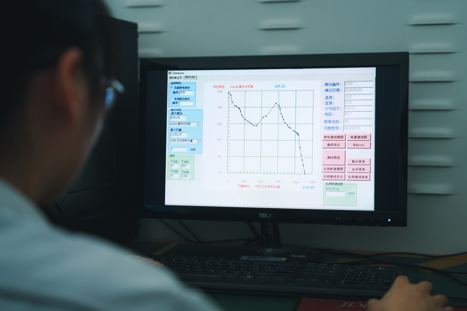
Engineer reviewing fan P-Q curve test data on analysis software showing pressure-flow performance measurements for 28VDC avionics fan evaluation
P-Q curve data analysis: measured pressure-flow data reviewed against datasheet baseline values before fixture testing of a 28VDC avionics cooling fan candidate.

Pressure conversion matters in a real evaluation. 3.6 inH2O is approximately 91.4 mmH2O or 897 Pa. This means PCG-6025-28-AF is a useful 28VDC reference model, but it should not be described as pressure-equivalent to an Aximax 2-class fan unless operating-point fixture testing proves the target system does not require the full public shutoff-pressure range.

Same-fixture test method

The evaluation should be run with both fans under identical conditions:

  • Same regulated voltage supply, set to the platform nominal, such as 28VDC.
  • Same inlet and outlet condition.
  • Same duct or impedance fixture representing the real equipment resistance.
  • Same ambient temperature.
  • Same warm-up duration before steady-state readings.
  • Same airflow and pressure measurement locations.
  • Same current probe and waveform capture method.
  • Same RPM or status monitoring method, where available.

Startup current should be captured as a waveform, not read from a multimeter. BLDC fans can draw short-duration peak current during startup. If a replacement candidate has a different peak-current profile, it may trip a current-limited supply even if steady-state current is acceptable.

Recommended operating-point test record

The following record structure can be used during fixture testing. Values should be measured under the same supply, inlet, outlet, fixture, and instrumentation conditions for both fans.

Measurement itemWhat to recordWhy it matters
28VDC free-air airflowAirflow with zero added system resistanceBaseline reference only
Operating-point airflow, impedance AAirflow and pressure at the first representative system resistanceShows installed cooling capability
Operating-point airflow, impedance BAirflow and pressure at a second representative system resistanceIdentifies curve sensitivity under restriction
Startup peak currentPeak current and duration from waveform captureConfirms supply sizing and brownout risk
Steady-state currentCurrent after warm-up at the operating pointConfirms power budget and thermal loading
RPM or status feedback stabilityFG pulse behavior or RD/status state under loadConfirms monitoring compatibility
Noise at operating pointSound pressure level at a defined distanceSupports crewed-platform and enclosure reviews
High-temperature operationSoak condition, runtime, current, speed, and airflowConfirms thermal derating behavior
Low-pressure or altitude conditionPressure or altitude condition, density correction, and airflowConfirms performance under reduced air density

Interface behavior is part of the evaluation

Signal behavior is often where replacement programs fail.

FG, RD, and PWM are not interchangeable. FG outputs a pulse train for speed calculation. RD outputs a run or status state. PWM controls speed and should reference the fan negative. Feedback lines from multiple fans should not be paralleled unless the circuit is specifically designed for that configuration.

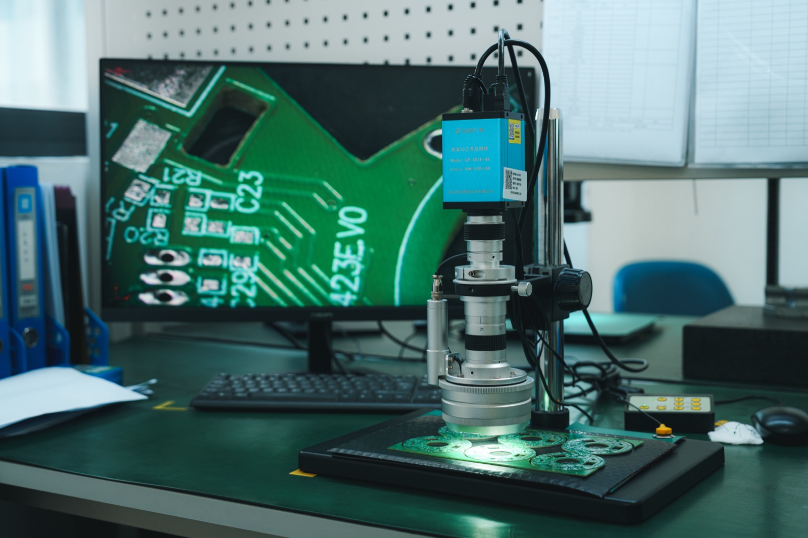
Digital microscope inspection of PCB interface connections for FG RD and PWM signal verification on a 28VDC BLDC avionics cooling fan
Interface inspection: digital microscope verification of PCB signal connections for FG, RD, and PWM lines, confirming pinout and signal-level compatibility before replacement qualification.

For PCG-6025-28-AF, the reference configuration uses PWM speed control and RD status output. For PCG-8038-28-AF, the reference configuration uses PWM speed control and FG speed feedback. If the target AMETEK configuration uses a fan performance sensor or another status output, the monitoring interface should be reviewed before assuming compatibility.

Qualification risk review

Risk areaWhat can go wrongEvidence required
Same free-air CFM, lower operating-point airflowCurve mismatch under impedanceP-Q overlay and fixture test
Lower shutoff pressureCandidate cannot overcome platform resistanceSystem resistance curve
Different startup currentSupply trips or brownout occursStartup waveform
Different FG/RD/status behaviorHealth monitoring failsInterface circuit review
Similar envelope but different mounting loadsResonance or fatigueDrawing overlay and vibration review
Unverified EMI/EMC behaviorPlatform-level interference riskTest report or pre-compliance data
Different connector or wire configurationInstallation rework requiredHarness and connector review

RFQ checklist for replacement evaluation

To evaluate a 28VDC avionics fan against an AMETEK Rotron Aximax reference, provide:

  • Target AMETEK Rotron part number.
  • Target fan datasheet or drawing.
  • Available envelope and mounting constraints.
  • Rated voltage and allowed input range.
  • Required airflow at operating pressure, not only free-air CFM.
  • System impedance or duct restriction information.
  • Heat load in watts and allowed temperature rise.
  • Platform type: aircraft, radar, UAV, naval, ground vehicle, or ground station.
  • Operating temperature range.
  • Altitude or low-pressure condition.
  • Vibration and shock profile, or RMS level if available.
  • EMI/EMC requirements.
  • Required feedback or control signals: FG, RD, PWM, CAN, RS485, RS422, or RS232.
  • Connector and cable constraints.
  • Expected annual quantity and qualification stage.

Conclusion

Do not describe a 28VDC fan as a drop-in replacement for an AMETEK Rotron Aximax reference unless dimensions, voltage range, connector, mounting, operating-point airflow, pressure capability, signal interface, and qualification conditions are all verified.

PCG-6025-28-AF is the most relevant PERSEUS public reference model for this evaluation because it shares the 28VDC avionics bus range and compact axial format. PCG-8038-28-AF and PCG-12038-28-AF should be used as adjacent higher-airflow references for chassis cooling studies, not as direct Aximax 2 replacements.

The defensible engineering question is not "which fan has the higher catalog CFM?" It is "which fan delivers the required airflow at the system operating point while matching the platform's electrical, mechanical, and qualification constraints?"

FAQ

Can PCG-6025-28-AF be called a drop-in replacement for AMETEK Rotron Aximax 2?

No. It can be used as a PERSEUS public reference model for evaluation, but not as a drop-in replacement unless the exact AMETEK part number, mounting envelope, connector, signal behavior, P-Q curve, operating-point airflow, and qualification conditions are all verified.

Why is free-air CFM not enough?

Free-air CFM is measured at zero pressure. Real avionics enclosures include filters, ducts, heat sinks, grilles, and compact board spacing. The installed airflow is determined by the operating point where the fan curve intersects the system resistance curve.

Why does shutoff pressure matter?

Shutoff pressure indicates the pressure end of the fan curve. A fan with similar free-air airflow but lower pressure capability may underperform in a high-impedance enclosure. For reference, 3.6 inH2O is approximately 91.4 mmH2O or 897 Pa.

Are FG and RD signals interchangeable?

No. FG is a pulse output used for speed calculation. RD is a run or status output. A monitoring circuit designed for one signal type may not correctly interpret the other.

What information is needed for a real comparison?

At minimum: exact target part number, fan drawing, voltage range, P-Q curve, system impedance, required operating-point airflow, startup current constraints, signal interface, connector details, temperature range, altitude condition, vibration profile, and EMI/EMC requirements.

References

Written By

Perseus product image

Perseus Engineering Team

Perseus technical content is reviewed for relevance to defense electronics cooling, rugged thermal management, and international qualification requirements before publication.