
RFQ Request a Quote
Home
Expand
Technical Resources
Expand
Technical Notes

Fan Speed Control for Military Electronics: PWM, Voltage and Temperature Control Compared

August 19, 2026 Author:Dr. Du

The Physics: Why Speed Control Beats Everything Else

Fan speed control matches airflow to the load the system actually sees — and pays back three times. A variable speed dc fan runs quieter at partial load, draws less power, and extends bearing life. The leverage comes from physics: fan power scales with the cube of speed, so a 10% speed cut removes roughly 27% of the input power. This note explains the speed relationships, the measured noise benefit, the control signals and feedback wiring, and the circuit-design practices that keep a pwm dc fan stable in a military electronics environment.

Three relationships govern every fan, whether it is a 40 mm avionics cooling fan or a brushless DC blower in a ground-vehicle cabinet:

Quantity Relationship to Speed Effect of 10% Speed Cut
Airflow (Q)Proportional to speed (N)−10% airflow
Static pressure (P)Proportional to speed² (N²)−19% pressure
Input power (W)Proportional to speed³ (N³)−27% power

The cubic term is the whole story. Most electronics spend their life well below worst-case thermal load, which means a pwm controlled fan spends most of its life at a speed far below maximum — where the power and noise savings concentrate. No other thermal lever recovers this much energy for this little cost.
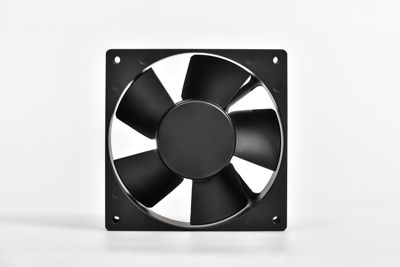
Noise Reduction from Speed Derating

Acoustic noise falls predictably with speed. The measured reductions at each derating step:

Speed Reduction Noise Reduction
50%15 dBA
40%11 dBA
30%8 dBA
20%5 dBA
10%2 dBA

Fifteen dBA is not a small change — it reads to the ear as roughly one-third of the original loudness. In practice, a fan derated to half speed in idle duty keeps most enclosures well within acoustic limits while losing an airflow margin the thermal budget rarely used. If the mission profile includes long standby or low-power modes, speed control is the cheapest acoustic treatment available. The derating values above are measured on representative Perseus models at fixed system impedance; at deep derating, bearing and motor noise begin to dominate, so the reduction is model-specific and flattens rather than following a pure logarithmic curve.

Closed-Loop Control Architecture

Modern fan control runs a four-step closed loop: temperature acquisition → controller analysis → actuator adjustment → status feedback.

Step Function
Temperature acquisitionMonitor system or board temperatures via thermistors or remote sensors
Controller analysisCompare temperature against the target band
Actuator adjustmentChange fan speed via voltage, PWM, or temperature-based control
Status feedbackReturn tachometer (FG) and alarm (RD) signals to the host

The control logic itself is deliberately simple: above the target band, increase speed; inside the band, hold speed; below the band, decrease speed. The band — not a single threshold — is what prevents hunting. Without hysteresis, a fan parked near one setpoint oscillates between speeds, and the acoustic signature is worse than steady full speed.

Control Signal Options

Three input types cover virtually every military and industrial application:

Signal Type Function Typical Use
Voltage controlAnalog speed setting via supply or control voltageSimple 2-wire systems, legacy platforms
Temperature controlAutomatic speed response to a thermistor inputStandalone cooling without a host controller
PWM controlDigital duty-cycle speed control28VDC avionics, smart cooling with host control
DC cooling fan with multi-conductor cable harness providing PWM input and FG tachometer and RD alarm feedback wires
A pwm dc fan with its control and feedback harness. The additional conductors carry PWM input, FG tachometer output, and RD alarm output back to the host controller.

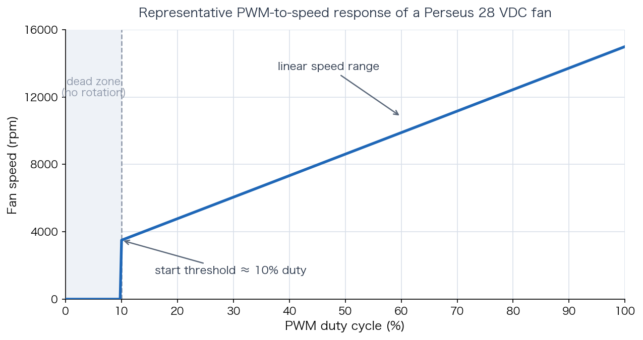
The PWM-to-speed response is not linear from zero. A representative 28VDC unit stays at rest until roughly 10% duty cycle, starts at about 3,500 rpm, then scales linearly to its full-speed rating:

PWM duty cycle versus fan speed curve showing dead zone below 10 percent duty and linear speed range up to full speed
Representative PWM-to-speed response of a 28 VDC fan. Below the ≈10% start threshold the rotor does not turn; above it, speed scales linearly with duty cycle. Plan control ranges above the start threshold.

Feedback Signals: FG and RD

Speed control without status feedback is open-loop in the worst sense — the host has no way to know the fan stopped. Two outputs close this gap:

  • RD (rotation detection / alarm): a level signal indicating whether the fan is rotating. In a dc fan with rd alarm output, the signal changes state on stall, giving the host a simple pass/fail status line for health monitoring.

  • FG (frequency generation / tachometer): a pulse train proportional to rotor speed. A dc fan with fg signal lets the host compute actual rpm — commonly two or four pulses per revolution — and detect gradual speed degradation before it becomes a failure.

  • Bus interface feedback: for multi-fan systems, controller-based status reporting over RS485, CAN, or RS422 aggregates per-fan speed, alarms, and fault prediction on a single interface.

Circuit Design Practice

The signal interface is where speed-control programs succeed or fail in the field. Four practices from Perseus application engineering are worth building in from the start:

  1. Do not drive fan signal lines directly from an MCU IO pin. Signal lines should be isolated or buffered — optocoupler isolation, a level-shifter chip, or transistor interface — because conducted transients on long fan cable runs can destroy a processor port.

  2. Add transient protection at the interface. TVS diodes or zener clamps on control and feedback lines, plus common-mode chokes where the fan sits far from the controller, keep EMI and surges out of the logic domain.

  3. Respect the sink-current limit. Open-collector FG and RD outputs typically sink 10 mA or less; size the pull-up resistor accordingly (the internal pull-up in many units makes an external one unnecessary).

  4. Share the fan's reference ground. The signal reference is the fan's negative supply. If the controller ground is not common with the fan negative, speed commands go uncontrolled and feedback reads erratic — a wiring error that mimics a fan fault.

Smart Fan Controllers

Where a platform runs multiple fans, a dedicated controller removes the per-fan interface burden from the host. Perseus intelligent fan controllers communicate over bus protocols (RS485, CAN, RS422), accept host commands, and report per-fan speed, status, and fault-prediction data:

Supply Range Monitored Channels
12–48 VDC8 fans
20–52 VDC6 fans
220 VAC6 fans

Integrated fan modules go one step further — fan, temperature sensing, and control board in one assembly with dual-mode speed control (automatic temperature tracking plus manual override), which simplifies both installation and maintenance on platforms where access is limited.

Frequently Asked Questions

Q: PWM or voltage control — which should I use?

A: PWM fan vs voltage control comes down to efficiency and interface. Voltage control is simple and robust but wastes power in the regulation stage and offers poor low-speed linearity. PWM holds torque at low speeds, integrates cleanly with a host controller, and is the standard for 28VDC avionics cooling fan applications. Use voltage control mainly on legacy 2-wire interfaces.

Q: How much can I slow a fan before cooling suffers?

A: Verify against the fan's P-Q curve and your system impedance curve, not a rule of thumb. As a planning number, a 20% speed cut costs about 20% airflow and 36% pressure but returns 49% input-power savings and 5 dBA of noise. Keep the operating point above the start threshold and away from the stall region.

Q: What is the cheapest way to reduce fan noise in an existing enclosure?

A: If the fans already carry PWM or FG wiring, re-tune the control band before changing hardware. Most systems are commissioned with conservative setpoints; raising the full-speed trigger a few degrees often derates the fans for most of the duty cycle. That is why "how to reduce fan noise" usually ends at the control table, not at the fan catalog.

Q: Can I add speed control to an existing fan?

A: Only if the fan supports it. A 2-wire fan cannot be PWM-controlled externally without risk; a 3-wire fan (FG) reports speed but cannot be commanded; a 4-wire fan (PWM + FG) does both. In replacement programs on legacy platforms, confirm the new fan preserves the original control interface (voltage, PWM, or FG/RD signals) so the host controller needs no redesign — matching the existing wiring and control scheme avoids a control board redesign.

Related Articles

Perseus designs and manufactures military-grade cooling fans and intelligent fan control systems — pwm dc fans, brushless DC blowers, and controller modules with FG/RD feedback and RS485, CAN, or RS422 interfaces for defense and aerospace platforms. For speed-control interface matching, control-circuit review, or a custom military cooling fan quotation, contact our engineering team.

Technical basis: Perseus fan control application data (28 VDC fan control programs, measured noise derating, controller specifications). Speed relationships follow the affinity laws for axial fans; confirm derating limits against the selected model's P-Q curve and datasheet. Reviewed August 2026.

Written By

Perseus product image

Dr. Du

Dr. Du is a thermal engineering designer at Perseus, specializing in forced-air cooling design and high-static-pressure DC fan selection for military and defense electronics. He leads airflow configuration and fan curve optimization reviews for rugged cooling applications.