



Cooling fans in defense and aerospace electronics usually fail in recognizable patterns. The useful diagnostic question is not only whether a fan has stopped, but what changed first: electrical current, commutation, mechanical noise, vibration, or airflow.
This engineering note organizes common fan failure modes by symptom, root cause, and corrective action. It is intended for system designers, reliability engineers, and maintenance teams selecting or troubleshooting axial and centrifugal cooling fans in high-density electronics.
Symptom-Based Quick Reference
Use the observed symptom to narrow the first inspection. Confirm the result against the applicable product datasheet and the installed system conditions.
| Observed symptom | Likely cause | First check |
|---|---|---|
| Fan stops completely | MOSFET or drive-circuit failure; motor burnout | Supply voltage, start current, thermal derating margin |
| Fan starts and then locks | Locked rotor, obstruction, or bearing seizure | Impeller clearance, obstruction, bearing condition |
| Abnormal noise | Bearing wear, frame resonance, or mounting stress | Mounting torque, isolation hardware, structural resonance |
| Speed fluctuation | PWM/control-signal issue or capacitor degradation | Control signal integrity, supply stability, ESD exposure |
| Fan runs but airflow is low | Impeller damage, blockage, or system impedance above the design point | Air path, impeller condition, installed pressure drop |
| Tachometer or status signal is abnormal | Wiring error, ESD damage, or signal-line interference | Wiring, grounding, TVS/varistor protection |
Failure Mode Matrix
1. Electronic Component Failure
Electronic failure is common in electronically commutated and brushless fans. The drive MOSFET and related components must withstand the fan's inductive current profile, start-up demand, switching stress, and installed temperature. Peak current can be approximately 1.5 to 3 times the average current, depending on the operating point and control strategy.
| Failure mode | Typical root cause | Corrective action | Typical status |
|---|---|---|---|
| MOSFET failure | Insufficient design margin or high-temperature operation | Increase derating margin and select a product rated for the actual duty cycle | Fan stops |
| MOSFET failure | Overvoltage or transient stress | Match the fan to the supply characteristics and add TVS protection where appropriate | Fan stops or locks |
| Capacitor or component failure | Soldering defect, mechanical stress, or thermal cycling | Strengthen process control and use appropriate screening and qualification tests | Fan stops or behaves abnormally |
| Signal-function failure | Wiring error, ESD, or electrical overstress | Verify wiring and add ESD protection to PWM and tachometer lines | Status signal abnormal |
| EMI-related disruption | Strong RF environment or inadequate shielding | Improve shielding, grounding, filtering, and ESD protection | Intermittent stop or abnormal output |
2. Motor Failure
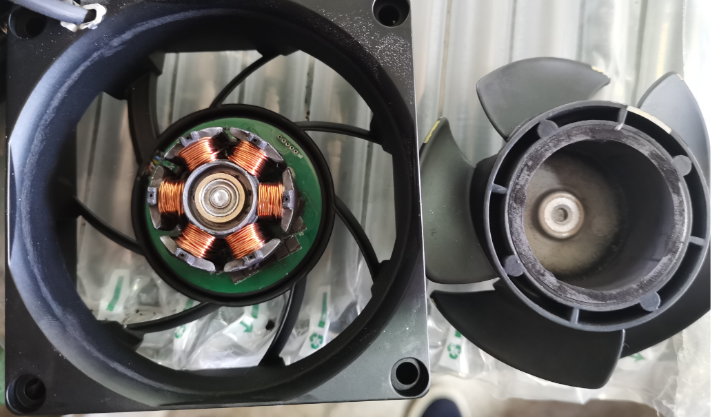
Motor failures are often associated with excessive temperature, voltage outside the specified range, foreign-object interference, or damage to the winding and connection structure. A current measurement taken during start-up and steady operation can help distinguish a locked rotor from a drive-circuit fault.
| Failure mode | Typical root cause | Corrective action | Typical status |
|---|---|---|---|
| Motor burnout | Winding damage, voltage outside range, overtemperature, or foreign-object jamming | Verify process control, operate within specification, and use a protective grille where required | Fan stops or current becomes abnormal |
| Coil or connection break | Winding breakage or connection failure | Improve motor production, soldering, and assembly controls | Fan stops |
3. Frame and Impeller Failure
Frame and impeller damage can result from improper installation, excessive shock or vibration, foreign objects, or a mismatch between the fan qualification level and the installed mechanical environment. A damaged impeller can reduce airflow even when the motor continues to run.
| Failure mode | Typical root cause | Corrective action | Typical status |
|---|---|---|---|
| Frame structural damage | Mounting error, excessive mechanical exposure, or foreign objects | Correct the mounting method, match the product to the environment, and add a grille where needed | Stop, lock, or abnormal noise |
| Impeller damage | Foreign objects or excessive shock and vibration | Protect the air path and select a fan qualified for the actual mechanical environment | Stop, lock, or abnormal noise |
| Shaft or hub detachment | Excessive mechanical loading or impact | Review the mechanical environment and select an appropriate construction | Fan stops or locks |
4. Bearing and Wiring Failure
Bearing noise, poor rotation, and intermittent signals can originate from both the component and the installation. Preload, interference, mounting resonance, cable routing, and corrosion should be evaluated together rather than treated as isolated issues.
| Failure mode | Typical root cause | Corrective action | Typical status |
|---|---|---|---|
| Lead-wire break | Corrosion, insufficient strain relief, or installation damage | Improve routing and strain relief; match materials and protection to the environment | Fan stops |
| Bearing noise, lock, or poor rotation | Preload or structural interference; resonance or mechanical amplification | Adjust the design, match the product to the application, and control mounting torque | Noise, lock, or poor rotation |
Environmental and Installation Case
In outdoor or coastal installations, salt fog, humidity, and airborne particulates can accelerate degradation of electronics, bearings, connectors, and exposed metal surfaces. The risk is higher when environmental protection, grounding, and air-path protection are treated as separate design tasks.
Recommended corrective actions include:
Use a conductive shielding grille and provide a low-impedance chassis-ground path.
Place appropriate EMI filtering at the front stage of the power and signal interfaces.
Review sealing, connector protection, corrosion resistance, and maintenance access for the installed environment.
How to Read a Current Waveform During Diagnosis
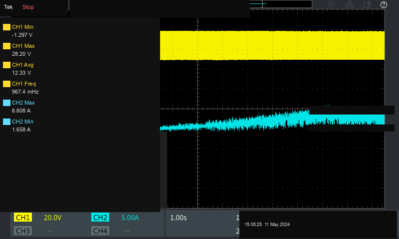
An oscilloscope measurement can reveal conditions that a static voltage check will miss. Compare start-up current, steady-state current, commutation behavior, and transient peaks against the fan specification and the system power budget. A current waveform with high peaks, unstable commutation, or excessive noise can indicate insufficient supply margin, wiring problems, mechanical loading, or EMI coupling.
Design Recommendations
Maintain thermal margin. MOSFET reliability is strongly affected by junction temperature. Apply the derating method specified for the selected product; as a practical design target, avoid operating close to the rated thermal limit.
Protect the supply. Fans are inductive loads. Evaluate TVS diodes, MOVs, current limiting, and transient behavior for the complete power path.
Match the mechanical qualification. A fan qualified for one vibration or shock level should not be assumed to tolerate a more severe installed environment. Select the product and isolation hardware from the actual platform requirements.
Control environmental exposure. For outdoor or coastal applications, evaluate sealing, grille design, grounding, corrosion protection, and service intervals as one system.
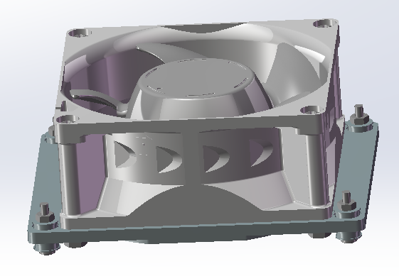
Control mounting stress. Use the flange and fastener arrangement intended for the fan construction, and verify torque and flatness so the frame is not distorted during installation.
Additional Engineering Notes
Typical reference MTBF ranges for military cooling fans can reach 70,000 to 150,000 hours at 40°C, but the applicable value must be confirmed for the specific model, duty cycle, temperature, and qualification method.
As ambient temperature rises above the rated point, available life and reliability margin decrease. Do not substitute a generic temperature rule for the model-specific reliability data.
Bearing noise may result from preload, interference, resonance, or mechanical amplification. Isolation mounts and controlled torque procedures can remove many installation-related causes.
Strong RF environments can couple into PWM and tachometer lines and disrupt commutation or status output. Shielding, grounding, and front-stage filtering should be reviewed together.
TVS devices or varistors may be appropriate on power and signal lines when selected for the actual transient environment. Verify the protection network does not interfere with the control interface.
Conclusion
Reliable fan selection is a system-engineering task. Electrical margin, airflow resistance, temperature, vibration, shock, EMC, environmental exposure, mounting, and service access all influence the result. A symptom-led inspection combined with current-waveform measurement and model-specific qualification data can shorten troubleshooting and prevent repeat failures.
Perseus supports application-specific selection of military-grade cooling fans, centrifugal blowers, fan-drive electronics, retention hardware, and integrated thermal-management assemblies. Contact our engineering team with the required airflow, static pressure, voltage, control interface, temperature range, mechanical environment, and qualification targets.