
Contact us
Home
Expand
Technical Resources
Expand
Technical Notes

How to Size EMI Shielding Vents for Military Electronics: Waveguide Cutoff Frequency Formulas and Design Rules

August 10, 2026 Author:Perseus Engineering Team

TL;DR

Improperly sized vent apertures are one of the most common causes of MIL-STD-461 RE102 failures in fielded military electronics. This guide provides the cutoff frequency formulas, shielding effectiveness calculation, ventilation cross-check, and a worked example so engineers can size vents correctly before qualification testing.
Why Cooling Vents Are Your Biggest EMC Risk

A single unsized vent aperture can cause an RE102 test failure that no amount of board-level filtering will fix. Vent apertures act as slot antennas — the larger the opening relative to the wavelength, the more RF energy radiates out (or couples in). Waveguide-below-cutoff vents solve this by making the aperture behave as a high-pass filter with a defined cutoff frequency.

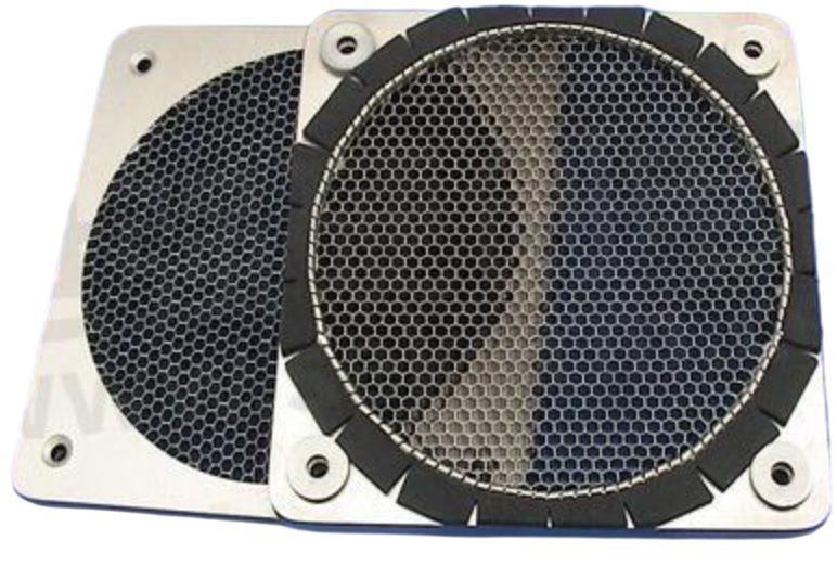
EMI shielding honeycomb vent panels showing hexagonal cell geometry for waveguide-below-cutoff RF attenuation
Figure 1. EMI shielding honeycomb vent panels. The hexagonal cell geometry creates waveguide-below-cutoff apertures that attenuate RF energy while maintaining airflow. Cell size, depth, and count are the three design variables.

The Two Core Formulas

Aperture TypeFormulaVariables
Circular waveguidefc = 6900 / Dfc in MHz, D = diameter in inches
Hexagonal honeycombfmax ≈ 15 / Wfmax in GHz, W = aperture width in mm

Design rule: The cutoff frequency fc must be at least 3× the highest frequency to be shielded.

Shielding Effectiveness vs. Depth

Attenuation increases with the ratio of vent depth to aperture size:

SE ≈ 20 × (depth / aperture) + 10 (dB)

Design rule: Vent depth must be ≥ 3× the aperture width to ensure adequate attenuation below cutoff.

Depth / Aperture RatioApproximate SE
~30 dB
~50 dB
~70 dB
~90 dB

Ventilation Cross-Check

Shielding effectiveness means nothing if the vent starves the fan. Always verify:

Total vent area = n × single cell area

Design rule: Total ventilation open area must be ≥ 1.2× the fan outlet area.

If ventilation fails the check: increase cell count first (not aperture size — enlarging apertures degrades shielding).

Full Design Workflow

  1. Define highest frequency requiring shielding.

  2. Calculate max aperture size: W ≤ 15 / (3 × f_target).

  3. Set vent depth ≥ 3× aperture width.

  4. Calculate total open area, verify ≥ 1.2× fan outlet area.

  5. If ventilation fails → increase cell count, re-verify shielding.

Worked Example: Sizing a Vent for 2.4 GHz Shielding

Requirement: Shield internal clock harmonics up to 2.4 GHz. Fan outlet area: 40 × 40 mm.

Step 1 — Maximum aperture width:

fc ≥ 3 × 2.4 GHz = 7.2 GHz
W ≤ 15 / 7.2 = 2.08 mm → select W = 2.0 mm

Step 2 — Minimum vent depth:

depth ≥ 3 × 2.0 mm = 6.0 mm

Step 3 — Ventilation check:

Fan outlet area = 40 × 40 = 1,600 mm²
Required vent area ≥ 1.2 × 1,600 = 1,920 mm²
Single cell area (circular, r = 1.0 mm) = π × 1.0² = 3.14 mm²
Cells needed ≥ 1,920 / 3.14 ≈ 612 cells

Result: A honeycomb vent with W = 2.0 mm apertures, 6.0 mm depth, and at least 612 cells meets both the 2.4 GHz shielding requirement and the ventilation requirement.

Perseus Recommended Aperture Sizes

In practice, Perseus recommends 3.2–5.6 mm apertures for most military electronics applications, balancing shielding performance against ventilation efficiency. For systems requiring shielding above 1 GHz, apertures of 2.0–3.2 mm are used with increased cell counts to maintain airflow.

ApplicationRecommended ApertureShielding Coverage
General military electronics5.6 mmUp to ~900 MHz
Radar / EW systems3.2 mmUp to ~1.6 GHz
High-frequency avionics2.0 mmUp to ~2.5 GHz

EMC Qualification Scope

Perseus fans and vent systems are designed with EMC shielding considerations, with testing available to MIL-STD-461 requirements for specific applications. The relevant EMC test methods and their typical scope include:

TestScope
RE102 radiated emissions10 kHz – 18 GHz
CE102 conducted emissionsFull naval/army/air force frequency range
Power surge suppression50V and 80V transients per MIL-STD-704 / RTCA/DO-160
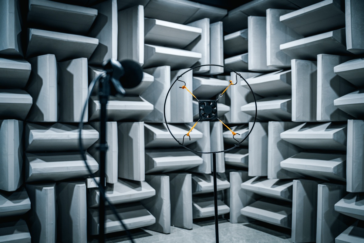
Perseus anechoic chamber facility used for EMC testing of military cooling fan systems
Representative Perseus testing facility. EMC qualification scope is established for the selected model, configuration, and agreed test plan.

FAQ

Can I use a standard commercial honeycomb vent for MIL-STD-461 RE102 compliance?

Only if the aperture size and depth meet the cutoff frequency and SE requirements for your specific frequency range. Most commercial vents are not sized for RE102 — verify with the formulas above before assuming compliance.

Does increasing vent depth always improve shielding effectiveness?

Yes, but with diminishing returns above a depth/aperture ratio of 4×. Beyond that point, the dominant leakage path shifts to peripheral gaps and seams rather than the vent apertures themselves.

What is the shielding effectiveness of a typical military honeycomb vent?

A properly sized honeycomb vent (depth/aperture ratio ≥ 3×) achieves 60–80 dB SE across the RE102 frequency range. This eliminates the need for additional conductive gaskets in most applications, reducing cost and weight.

Related Articles

Perseus designs and manufactures military-grade cooling fans and thermal management systems with EMC design support available for MIL-STD-461 and related requirements. For EMC vent design support, contact our engineering team.

Technical basis: MIL-STD-461 (RE102, CE102), MIL-STD-704, and RTCA/DO-160. This guide explains vent design principles and does not assign a universal qualification level to every Perseus product. Confirm all ratings against the selected model, configuration, datasheet, and approved test report. Reviewed August 2026.

Written By

Perseus product image

Perseus Engineering Team

Perseus engineering team provides thermal management solutions for defense, aerospace, and industrial applications, with expertise in MIL-STD-810H, MIL-STD-461, and RTCA/DO-160 compliance.