RFQ Request a Quote
Home
Expand
Technical Resources
Expand
Technical Notes

Cooling Pulsed Loads in a Rugged Chassis: Phase-Change Storage vs. TEC vs. Liquid Cooling

October 12, 2026 Author:Perseus Thermal Control Division

Two Numbers, Not One: Peak Power vs. Average Power

A burst-mode embedded compute card, a pulsed RF amplifier, a radar module and a lidar payload share the same thermal signature. Each draws high instantaneous power for a few seconds, then drops to near idle for a much longer period — and each lives in a rugged chassis whose cooling budget was set long before the payload was final.

Teams that size thermal hardware on peak power build oversized systems. A 2 kW load that runs for 30 seconds out of every 300 does not need 2 kW of continuous rejection. It needs about 200 W of steady rejection, plus a way to bridge the gap between that steady capability and the instantaneous load.

The two numbers describe two different pieces of hardware, and mixing them up is the most common error in chassis thermal design for pulsed loads.

QuantityValue
Peak power2,000 W
Pulse duration30 s
Idle interval270 s
Pulse energy60 kJ
Cycle length300 s
Average power200 W
Duty cycle10%

The 2,000 W figure describes the cold plate and the heat-spreading path immediately under the source: conduction into the module baseplate and the chassis wall. The 200 W figure describes the heat exchanger, the fan or pump, the acoustic budget and the enclosure sealing. Designing for 2 kW continuous means roughly ten times the rejection hardware, ten times the acoustic signature and a much larger envelope, for a load that spends 90 percent of its life doing nothing.
Three Ways to Bridge the Gap

There are only three physical mechanisms available, and most real chassis designs use two of them together.

Store the pulse instead of rejecting it. A phase-change material absorbs energy as latent heat at a nearly constant temperature. The buffer holds the temperature down during the pulse, and the steady-state path recharges it afterwards.

Raise the rejection temperature difference. A thermoelectric cooler or a small vapour-compression loop pumps heat uphill, so the load can be held colder than an ambient-referenced heat sink would otherwise allow.

Increase the transfer coefficient. Liquid cooling moves heat away from the source far faster than air, which keeps the source-to-coolant temperature difference small even at high heat flux.

Phase-Change Storage: A Battery for Heat

A phase-change pack does not remove heat. It stores it. That distinction determines how it has to be sized.

Because melting happens at a nearly constant temperature, the cold plate stays close to the phase-change temperature for the whole pulse, then drifts upward once the material has fully melted. Hold time is set by the pulse energy, not by the peak power. In a well-sized buffer, a compact sealed assembly holds source temperature within a few kelvin for minutes at a time, in a package that fits next to the module it protects inside a SWaP-constrained chassis.

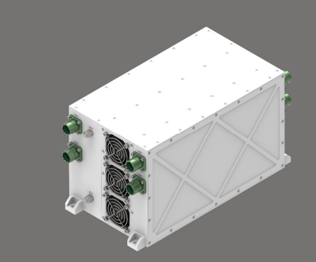
Sealed phase-change thermal storage module for rugged electronics

The relevant limit is not how much power the module can accept. It is how many joules it can absorb before the buffer is exhausted, and how quickly the steady-state path can reject them again before the next pulse.

That recharge requirement is where phase-change designs fail. Take the load above. During the 30-second pulse, the steady-state path removes about 6 kJ. The remaining 54 kJ has to go into the buffer:

60 kJ in − 6 kJ rejected = 54 kJ stored

At a latent heat of roughly 200 kJ/kg plus a 10 K sensible rise across the solid and liquid phases, effective storage lands near 220 kJ/kg, so the active material weighs about 250 grams, before containment and the spreading path that carries heat from the source into the material.

Those 250 grams then have to re-freeze. Rejecting 54 kJ over the remaining 270 seconds requires about 200 W of average rejection, which is exactly the average load. A phase-change buffer does not reduce the average duty on the heat exchanger. It flattens the peak. A buffer sized for the pulse but bolted to a heat sink or chassis wall that cannot recharge it will work once and then drift.

Phase-change storage is usually the right choice when the pulse is short, the average load is modest, the enclosure has to stay sealed and quiet, and there is no room for a pump.

Thermoelectric Cooling: Control, Not Capacity

A thermoelectric cooler moves heat from one face to the other when current flows through it, and reversing the current reverses the direction. That reversibility is genuinely valuable: the same module that cools a payload in a hot ambient can heat it during a cold start, which matters for equipment that has to operate from −40 °C — coincidentally also −40 °F.

It is worth being clear about what a thermoelectric cooler does not do. It does not create cooling capacity. It moves heat and adds its own electrical input power as additional heat on the hot side. A module pumping 45 W may add well over 100 W of extra heat that the same heat sink or liquid loop then has to reject. At large temperature differences the coefficient of performance falls below one, meaning the module adds more heat than it removes.

Packaged sealed thermoelectric assemblies span a few watts up to the low-hundred-watt class; beyond that the hot-side penalty dominates. At the low end, the common packaged form is a disc-style cooler that pairs a thermoelectric stack with a small frameless fan on the hot side, and the better assemblies switch automatically between heating and cooling according to ambient temperature.

Sealed thermoelectric cooling assembly with hot-side fans and heat sinks

The practical consequence: thermoelectric cooling is right when the load is small and the requirement is tight temperature control, not when the load is large and the requirement is bulk heat removal.

Two design points deserve attention. The input power of the cooler is part of the thermal budget, so an assembly should be specified on total heat rejected rather than on cooling capacity alone. And the cold face can drop below the dew point, so condensation control matters whenever the enclosure is not truly hermetic.

Pumped Liquid Cooling: Solving for Heat Flux

Air cooling fails at high heat flux long before it fails on total power. A source pushing past 100 W/cm² cannot be served by air at any reasonable flow rate, because the air-side film coefficient is simply too low. Liquid loops exist to fix that, and the useful way to think about them is that they solve for heat flux first and total power second.

A pumped loop has a second advantage with pulsed loads: the coolant inventory and the cold plate mass are themselves a thermal buffer. Sizing the loop on the average load and letting the coolant temperature swing a few kelvin across the pulse is often cheaper, lighter and more reliable than adding a separate storage material.

The arithmetic stays on your side, too. Even a compact 10 L/min water loop with a 5 K coolant rise absorbs roughly 3.5 kW continuously — more than fifteen times the 200 W average load in the example above. What constrains the design is not capacity. It is the heat flux at the cold plate, the coolant volume the installation can afford, and pump life against the maintenance interval.

Where no external coolant supply exists, a self-contained pumped loop with its own drive pump and heat exchanger removes the need for a vehicle-level cooling circuit — which is often exactly what makes liquid cooling feasible for standalone sealed subsystems and compact rugged chassis in the first place.

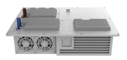
Self-contained pumped liquid cooling loop integrated into a rugged chassis

Choosing Between the Three

Phase-change storageThermoelectricPumped liquid
What it actually doesStores pulse energyPumps heat uphillMoves heat at high flux
Sized onPulse energy (J)Pumped watts and ΔTHeat flux and flow rate
Handles high peak powerOnly until the buffer is exhaustedPartiallyYes
Reduces average load on heat exchangerNoNo, it increases itNo
Moving partsNoneFan on hot sidePump
Can also heat the payloadNoYes, by reversing currentWith a heater
Adds its own waste heatNoYes, equal to input powerPump power only
Best fitShort pulses, sealed chassis, low average, no pump allowedTight control, small loads, cold start, sealedHigh heat flux, higher duty cycle, rack or platform level

A Specification Checklist for Pulsed-Load Chassis

Pulsed-load thermal problems are usually mis-specified rather than mis-designed. These are the inputs that change the answer:

  • Pulse profile: peak power, pulse duration, repetition interval, and whether the sequence is finite or continues indefinitely.
  • Pulse energy in joules. This is the number that sizes any storage element.
  • Average power in watts. This is the number that sizes the heat exchanger, the fan or the pump.
  • Heat flux at the source in W/cm². This is the number that decides whether air cooling is even possible.
  • Allowable temperature rise at the source, and its absolute limit. A processor die, a power amplifier and a machined housing tolerate very different excursions.
  • Ambient extremes at both ends, plus whether cold-start heating is required.
  • Sealing requirement. Hermetic enclosures rule out fans and make condensation a first-order concern for thermoelectric cooling.
  • Guaranteed idle time. A duty cycle quoted as "roughly eight minutes" is not a specification; if the idle interval can collapse, the buffer may never fully recharge.
  • Maintenance interval against pump life. A liquid loop is only as durable as its pump.
  • Where the heat is allowed to go: chassis-wall conduction, an internal fan path, or an external heat exchanger. This constrains everything upstream.

Three Questions Engineers Ask First

Can I just oversize the chassis fan instead? You can, and for a vented, noise-tolerant enclosure it is the simplest answer. You pay for it three times: louder acoustics, more continuous input power, and a bigger envelope. Where the chassis is sealed or acoustically limited, a high-static-pressure centrifugal blower buys back some of that cost, but it does not change the arithmetic — and one of the three bridging mechanisms above usually earns its place instead.

Does a phase-change buffer let me shrink the heat sink? No. It shrinks the peak path, not the average one. Size the steady-state path for the average load, size the buffer for the pulse energy, then verify that the buffer fully recharges between pulses. Both halves have to pass.

When is thermoelectric cooling worth the efficiency penalty? When the requirement is temperature control rather than bulk heat removal: holding a sensor or an optics block on a set point across ambient swings, cold-start heating, or a small sealed box where a silent solid-state assembly beats a compressor.

How These Choices Land in Real Chassis

All three mechanisms are standing options in our thermal management module family: sealed phase-change buffers that carry a module through its pulse, sealed thermoelectric assemblies for closed-loop control, and self-contained pumped loops for high-flux sources that air cannot reach. The right starting point is rarely a catalog pick. It is the three numbers in the table above — pulse energy, average power, heat flux. Bring those to the conversation and the architecture usually selects itself.

The Short Version

Pulsed loads are not harder to cool than steady loads, but they are easier to mis-size. Separate the peak from the average, size the heat exchanger on the average, size the bridge on the pulse energy, and check that the bridge recharges between pulses. Get those three numbers right and the architecture selects itself: liquid when heat flux is the constraint, phase-change storage when the chassis must stay sealed and quiet, and thermoelectric cooling when tight control and cold-start heating matter more than bulk capacity.

Written By

Perseus product image

Perseus Thermal Control Division

Perseus Thermal Control Division is the thermal design group at Perseus, responsible for chassis-level thermal management: phase-change storage, thermoelectric cooling assemblies and pumped liquid loops for rugged defense electronics.