

RFQ Request a Quote
Home
Expand
Technical Resources
Expand
Technical Notes

Cooling for Electronic Warfare: Specifying DC Fans for EW Pods and Radar Electronics

September 4, 2026 Author:Dr. Du

TL;DR

Cooling for electronic warfare (EW) pods and radar electronics is a thermal-management problem unlike any other in a mission system: high RF transmit power, dense digital signal processing, and tightly sealed enclosures all compete for the same small air volume. Electronic warfare cooling must handle power density that swings with every transmit burst, inlet air preheated by ram compression and solar load, altitude conditions that strip away most of the sea-level airflow, and a fan that lives next to a receiver sensitive to broadband EMI.

This engineering guide explains how Perseus engineering specifies DC fans for EW pod and radar cooling: how to read the thermal load, how to estimate required airflow, when to choose an axial fan versus a centrifugal blower, how to specify 28 VDC power input per MIL-STD-704, MIL-STD-1275, and MIL-STD-1399, and how to align control, telemetry, and electromagnetic / environmental behavior with the rest of the system. For the broader programme context, see the Perseus radar and electronic warfare cooling overview.

Cooling for electronic warfare systems comes down to four engineering decisions: heat-sink impedance (which dictates axial fan versus centrifugal blower), 28 VDC bus compatibility (per MIL-STD-704 for fixed-wing, MIL-STD-1275 for ground vehicles, MIL-STD-1399 for surface ships), the control and telemetry interface (PWM speed control, FG tachometer, RD alarm, optional health-management bus), and electromagnetic and environmental compatibility (MIL-STD-461G and MIL-STD-810H). Specify each of these with a model-specific evidence package. A generic "MIL-STD compliant" claim is not a substitute for a tested fan-and-controller combination in a representative enclosure.
Why EW Pods and Radar Electronics Are Different

Three characteristics separate EW and radar thermal management from a generic avionics fan application.

  1. Highly variable RF power dissipation. An active electronically scanned array (AESA) front-end can swing from idle (a few watts per T/R module) to peak transmit in microseconds. The cooling design must handle the worst-case thermal envelope, not just the steady-state average. Pulsed loading also drives thermal-cycling fatigue on the heat-sink-to-package interface, which in turn drives fan duty-cycle management.

  2. Receiver sensitivity sits next to the heat source. EW and radar receivers are vulnerable to broadband fan EMI, vibration-induced microphonics, and acoustic noise coupling into adjacent RF hardware. The fan is a neighbor, not an isolated sub-assembly, and it must behave as a quiet one.

  3. The pod envelope is small and the inlet air is hot. A wing-mounted or fuselage-mounted pod typically draws air heated by solar load, ram-air compression at cruise, and adjacent electronics. Altitude derating further reduces the fan's available pressure and flow at high operating ceilings: in the standard atmosphere, air density at 21 km is roughly 6 percent of the sea-level value, so the same fan wheel moves only a fraction of the mass flow it moves at sea level. The thermal margin the designer assumes at sea level rarely holds at altitude.

Each of these conditions shapes fan selection. For programme context, refer to the Perseus EW and radar cooling applications overview.

Thermal Loads: From the RF Front-End to the Signal Processor

An EW pod or radar line-replaceable unit (LRU) typically stacks the following heat sources inside one or two shared airflow paths:

  • RF front-end / T/R modules. High transient dissipation, highly localised hotspots. GaN-based T/R modules at 30 to 60 percent efficiency at peak transmit are typical, and the corresponding heat density at the cold plate drives the airflow architecture decision more than any other subsystem.

  • Exciter, upconverter, and frequency synthesizer. Moderate, steady dissipation. Less sensitive to transient loading, but the phase-noise performance of the synthesizer is sensitive to local temperature gradients and to vibration from adjacent fans.

  • Digital signal processor and FPGA / GPU array. Broad, dense dissipation spread across a board. The board-level heat sink is usually the dominant airflow path.

  • Power conditioning (28 VDC to lower rails, DC-DC converters). Concentrated loss that must be ducted away from RF stages. A poorly placed converter can re-radiate its loss as a hot plume directly into the heat sink it is meant to be cooling.

Design practice: capture each source as a separate thermal budget line. Size the fan by the sum of the steady-state dissipation plus a margin for the worst-case RF burst, not by the average. The same model-specific evidence discipline that drives the operating-temperature envelope is laid out in the related Perseus technical note on environmental qualification of military cooling fans.

Airflow Architecture: Forced Air vs Conduction vs Liquid

Three architectures are realistic for EW and radar electronics.

  1. Forced air over heat sinks. The most common architecture. Lightweight, simple to integrate, easy to maintain. Best suited to LRUs with power dissipation in the 50 to 300 W range where heat-sink impedance is moderate. Most current-generation EW pods and ground / shipboard radar LRUs sit in this regime.

  2. Forced air through cold plates or heat pipes. Useful where the heat source is buried in a sealed RF section. A heat pipe or vapor chamber brings heat to a finned surface where a fan can reach it. Common in receiver-only or exciter LRUs where RF shielding must be continuous.

  3. Liquid cooling (cold plate plus pump). Reserved for high-power AESA pods and certain naval radar arrays where power density exceeds what air can move in the available envelope. Liquid cooling is outside the scope of this article, but the same DC fan selection logic applies to the pump-side cold-plate heat exchanger and to the rack-level airflow that rejects heat from the secondary loop.

The remainder of this article focuses on forced-air architectures, which remain the dominant case in current-generation EW pods and ground / shipboard radar LRUs.

Axial Fan vs Centrifugal Blower: Matching Static Pressure to Heat-Sink Impedance

Before choosing a fan type, estimate the airflow the thermal budget actually requires. For forced-air cooling at sea level, a useful first-order sizing rule is airflow per watt of dissipation, tabulated against the allowed air temperature rise through the enclosure:

Allowed air temperature rise Airflow per watt (sea level) 250 W LRU requires
10 °C (18 °F)≈ 0.18 CFM/W (0.31 m³/h per W)≈ 45 CFM (76 m³/h)
15 °C (27 °F)≈ 0.12 CFM/W (0.20 m³/h per W)≈ 30 CFM (51 m³/h)
20 °C (36 °F)≈ 0.09 CFM/W (0.15 m³/h per W)≈ 23 CFM (39 m³/h)

This is a first-pass screening number only: it assumes sea-level density, ignores fan heat, and says nothing about pressure. It tells you how much air you need; the system curve tells you which fan type can deliver it. Correct the airflow by the local air-density ratio for altitude operation (see the worked example below).

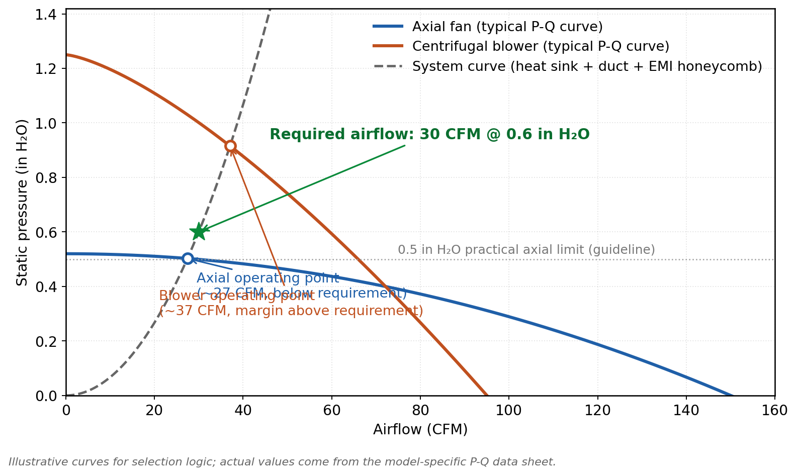
Once the airflow target is set, the fan type decision follows from one rule: select the fan by the system curve (heat sink plus duct plus filter pressure drop) and the operating point, not by airflow alone.

An axial fan moves high airflow at low static pressure. It suits shallow, low-impedance heat sinks, for example a finned cover or a small PCB-area heat sink, with open inlet and outlet conditions. A centrifugal blower (radial fan) moves less airflow at much higher static pressure. It suits dense, high-impedance heat sinks (tall fin stacks, restricted inlets, EMI honeycomb vent panels in the airflow path) and ducted airflow paths where the fan must push air through a confined channel.

Practical selection rule. If the heat-sink static pressure drop at the required airflow exceeds approximately 0.5 in H2O (about 125 Pa), an axial fan is usually a poor fit. Specify a centrifugal blower. If the pressure drop is below approximately 0.3 in H2O (about 75 Pa), an axial fan is generally the better choice and will deliver more airflow at a lower acoustic and vibration signature.

Air path characteristic Typical system pressure drop Recommended fan type
Open inlet, shallow heat sink, open outlet< 0.3 in H2O (75 Pa)Axial DC fan
Tall fin stack, single EMI honeycomb0.3 to 0.5 in H2O (75 to 125 Pa)Either, depends on size and noise target
Dense heat sink, ducted flow, two honeycombs, altitude operation> 0.5 in H2O (125 Pa)Centrifugal blower
High-altitude pod with ram-air preheat, multiple heat sinks, EMI honeycombs> 1.0 in H2O (250 Pa)High-static-pressure centrifugal blower
Illustrative P-Q curves comparing an axial fan and a centrifugal blower against a system curve, showing why the blower is selected when the required operating point sits above the axial fan capability
Figure 1. Illustrative P-Q curves. The required operating point (30 CFM at 0.6 in H2O) falls above the axial fan's capability, while the centrifugal blower delivers it with margin. Curves are illustrative; use the model-specific P-Q data sheet for a real selection.

Perseus product families for these two regimes.

  • PERSEUS small DC fans cover frame sizes from 40 mm to 120 mm square, thicknesses from 10 mm to 38 mm, voltage options of 5, 12, 24, and 48 VDC, with operating temperature -55 °C to +85 °C and IP54 to IP68 options depending on the model. They are the default starting point for compact EW modules, low-power radar receiver LRUs, and FPGA / DSP board-level cooling.

  • PERSEUS centrifugal fans (DC blowers) deliver higher static pressure for dense heat-sink stacks, ducted flow paths, and high-impedance EMI honeycombs in the air path. They are the default starting point for pod and high-altitude applications where the system curve sits well above what an axial fan can support.

Tip for the design review: always verify the fan operating point on the manufacturer's P-Q curve, not at free delivery. A fan running far to the right of its peak-efficiency point delivers less airflow than its nameplate suggests, and the system curve (heat sink plus filter plus honeycomb plus duct) defines the actual operating point. This is the same system-curve discipline we use when qualifying fans against MIL-STD-810H temperature, altitude, and vibration methods. See the related environmental qualification technical note for the evidence-package framework.

Worked Example: Sizing a Fan for a 250 W EW Receiver LRU

Requirement. A pod-mounted EW receiver LRU dissipates approximately 250 W (RF front-end 90 W, DSP board 120 W, power conditioning 40 W). The programme allows a 15 °C air temperature rise through the enclosure and defines a cruise altitude of 15,000 m. The air path consists of a dense cold-plate fin stack and one EMI honeycomb vent.

Step 1 — Required airflow at sea level. At 15 °C rise, the first-order rule gives 0.12 CFM/W. For 250 W: 250 × 0.12 ≈ 30 CFM (51 m³/h) at sea-level density.

Step 2 — System impedance. The dense fin stack plus one EMI honeycomb presents an estimated pressure drop of about 0.6 in H2O (150 Pa) at 30 CFM. This is an assumption for illustration; the real value comes from CFD or a prototype impedance test, and it should be measured, not guessed, before qualification.

Step 3 — Fan type. 0.6 in H2O is above the 0.5 in H2O threshold, so an axial fan is a poor fit. The correct starting point is a high-static-pressure centrifugal blower from the Perseus range, selected so that the 30 CFM at 0.6 in H2O operating point sits near the flat region of its P-Q curve, with roughly 20 percent flow margin held in reserve.

Step 4 — Altitude correction. At 15,000 m the standard-atmosphere density is roughly 16 percent of the sea-level value. Holding the same mass flow would demand about six times the volume flow, which no fan in this envelope can deliver. The realistic design response is to accept a larger air temperature rise at altitude, size the blower with speed headroom at sea level (PWM duty held below maximum), verify performance against the altitude profile per MIL-STD-810H Method 500.6, and escalate to a conduction-cooled or liquid-cooled architecture if the altitude thermal margin still fails. This is the point at which many pod programmes discover that a sea-level-optimized axial fan cannot be rescued at altitude, and a high-static-pressure blower plus a revised fin pitch is the cheaper correction.

Step 5 — Electrical and control interface. Specify 28 VDC nominal input per MIL-STD-704 with the steady-state range and transient envelope stated, PWM speed control to hold the margin in Step 4, and an FG tachometer so the LRU controller can detect the degraded-speed condition before it becomes a flight-line fault.

Result. A 28 VDC centrifugal blower selected by system curve at 30 CFM / 0.6 in H2O, with PWM speed control, FG telemetry, and altitude-verified performance, is the defensible specification for this LRU. The same five-step logic generalizes to other EW pod and radar cooling budgets by substituting the dissipation, temperature-rise allowance, and measured system impedance.

Power Input: 28 VDC per MIL-STD-704, MIL-STD-1275, and MIL-STD-1399

Most modern EW pods and radar LRUs run off a 28 VDC bus. The bus standard depends on the platform:

  • Fixed-wing aircraft. MIL-STD-704 defines the 28 VDC steady-state limits, ripple, and the transient over-voltage and under-voltage envelopes the fan must survive.

  • Ground vehicles. MIL-STD-1275 covers 28 VDC for military vehicles, including engine cranking surges and the conducted transient envelopes specific to vehicle power.

  • Surface ships and submarines. MIL-STD-1399 covers shipboard power distribution interfaces. Type I (28 VDC) and Type II (440 VAC) variants exist; a 270 VDC high-voltage DC bus, where used, is specified separately under MIL-STD-704 rather than MIL-STD-1399. Most radar and EW LRUs on smaller platforms use 28 VDC.

A fan that meets only commercial 24 VDC or 48 VDC input is not a drop-in replacement. Three things should appear on the fan data sheet.

  1. Steady-state operating range. A typical data-sheet operating window is 18 to 32 VDC for a nominal 28 V system (the MIL-STD-704 steady-state envelope for a 28 VDC bus is 22 to 29 V), and 36 to 60 VDC for a nominal 48 V system. PERSEUS DC fan models are designed for steady-state operation across 5, 12, 24, and 48 VDC rails.

  2. Transient tolerance. Surge and sag behavior consistent with the platform bus standard. A data sheet that only quotes a 24 VDC nominal point is missing the information the system integrator needs.

  3. Reverse-polarity and inrush protection. Both are common failure modes in fielded fans and are the kind of detail that distinguishes a qualified platform fan from a generic industrial fan.

For legacy fixed-wing and pod platforms that retain a 400 Hz AC distribution (115 VAC or 200 VAC), 400 Hz AC axial fan variants are also available. They are often specified alongside DC fans in a redundant cooling architecture, with the AC fan taking over on DC bus failure.

Control and Telemetry: PWM, Tachometer (FG), Alarm (RD), and Health Monitoring

Modern EW and radar LRUs use the fan as a managed thermal sub-system, not a passive blower. The minimum useful interface set is:

  • PWM speed control. Typically 0 to 100 percent duty cycle at 25 kHz or 1 kHz, signal level dependent. Allows the system controller to ramp fan speed in response to measured temperature, holding acoustic and vibration output low during standby and ramping up only when the thermal envelope demands it.

  • Tachometer (FG output). Open-collector pulse train, two or more pulses per revolution. Used by the system controller to detect stall, loss of speed, and degraded airflow. The FG signal is the basis for any active health-monitoring scheme.

  • Alarm / rotation-detect (RD output). Open-collector signal that goes low on stall. Simpler than FG, sufficient for a fail-safe signal to the LRU controller where a single binary "fan OK / fan failed" answer is all the system needs.

  • Health-monitoring bus. For higher-reliability systems, the same health data is sometimes exposed over a dedicated management bus or analog tachometer. For ATR-style chassis and 19-inch rack integrations where multiple fans are coordinated, an integrated fan-health-management module reports the aggregate status of the fan group to a single system controller.

Design note: always terminate FG and RD signals per the fan data sheet, treat them as pull-up-to-logic-rail outputs, and provide a software debounce. Field failures are often "noisy" rather than "missing", and a small amount of debounce plus runtime sanity checks makes the difference between a stable health signal and a controller that has to keep clearing phantom fan faults.

EMC, Shock, and Vibration: Aligning with MIL-STD-461G and MIL-STD-810H

EW and radar systems are the toughest neighbors any fan has to live with. Three categories of compatibility drive the design.

1. EMC, MIL-STD-461G. An electronic warfare cooling fan that radiates broadband noise on the DC bus, or via radiated emissions, can desensitize an adjacent receiver. PERSEUS DC fan designs incorporate EMC considerations in the design of the input filtering, common-mode behavior, and motor commutation strategy, with the intent of supporting the RE102 (radiated emissions, 10 kHz to 18 GHz) and CE102 (conducted emissions, 10 kHz to 10 MHz) limits of MIL-STD-461G. Where additional margin is required (for example, co-located with a high-sensitivity EW receiver), an external EMI filter on the DC input and a screened cable harness are the usual supplements. For the airflow path itself, an EMI honeycomb vent on the inlet and outlet is the standard approach. The detailed design rules for honeycomb-vent cutoff frequency, depth, and open area are covered in the related Perseus EMI shielding vents technical note. This article reflects Perseus's general engineering guidance for thermal management in airborne and naval electronic-warfare programmes. It does not assign a universal qualification level to every Perseus product; model-specific EMC evidence should be requested for each programme.

2. Vibration and shock, MIL-STD-810H. Pod-mounted fans see the full platform vibration spectrum and operational shock loads. PERSEUS DC fans are designed to support the environmental test methods of MIL-STD-810H procedures 514.8 (vibration) and 516.8 (shock), with ball-bearing and specially clamped rotor constructions available for high-shock platforms. Refer to the model-specific qualification report for the tested levels, axes, and durations applicable to your programme.

3. Temperature, altitude, humidity, salt fog, dust, and immersion, MIL-STD-810H. For fixed-wing pods, the platform typically defines an operating envelope of -55 °C to +85 °C with altitude operation up to approximately 21,350 m. For naval platforms, salt fog and humidity dominate. PERSEUS DC fan designs are intended to support the full MIL-STD-810H method set relevant to airborne, ground, and naval platforms. The methods most often invoked for EW and radar applications are:

MIL-STD-810H Method Environment Typical relevance
500.6Low pressure (altitude)Pod operation at high altitude
501.7High temperatureGround, shipboard, desert, and solar-loaded pod
502.7Low temperatureHigh-altitude and cold-soak start
503.7Temperature shockPod power-on after cold soak at altitude
506.6RainOpen-inlet pod and ground vehicle
507.6HumidityTropical, shipboard, and condensation exposure
508.8FungusLong-term storage in humid environments
509.7Salt fogNaval and coastal airborne platforms
510.7Sand and dustDesert, ground vehicle, and blowing-dust exposure
512.6ImmersionSubmarine mast-mounted and fording
513.8AccelerationHigh-performance aircraft and missile launch
514.8VibrationAll airborne, ground, and shipboard platforms
515.8Acoustic noiseEngine-adjacent pod and high-Mach flight
516.8ShockOperational shock, ballistic shock, crash shock
518.1Acidic atmosphereIndustrial and engine exhaust exposure
520.4Temperature, humidity, vibration, altitude (combined)Realistic mission profile
521.4Icing / freezing rainUnpressurised pod and ground radar
522.2Ballistic shockGunfire and weapon-launch shock
524.1Combined environments (tilt, transient, vibration)Shipboard and ground vehicle
525.1Time-domain waveform replicationMission-specific shock replication

The specific method, procedure, severity, and duration are tailored to the programme. The model-specific environmental qualification report should be reviewed during the design-in phase.

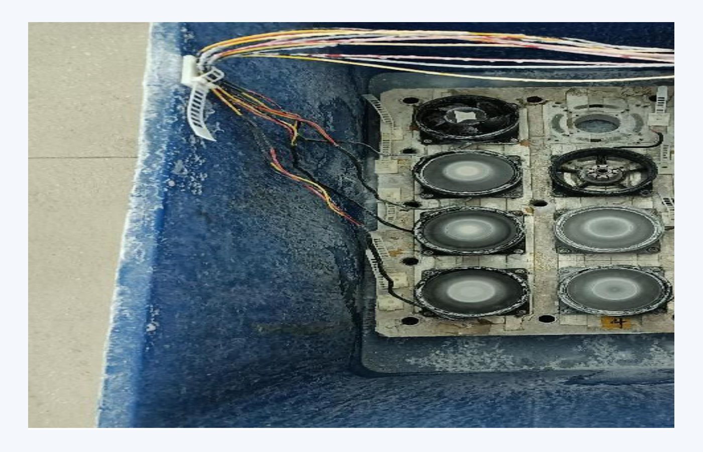
Perseus environmental test capability under MIL-STD-810H, including immersion testing relevant to submarine and naval radar line-replaceable units
Figure 2. Model-specific environmental evidence under MIL-STD-810H, including immersion testing (Method 512.6) relevant to submarine and naval radar LRUs. Humidity, salt fog, sand and dust, and thermal methods follow the same evidence-package discipline.

Perseus DC Fan Families for EW and Radar Cooling

Two product families cover the majority of EW pod and radar LRU cooling applications.

Small DC fans. See the Perseus small DC fan product family for the full model range.

  • Frame sizes from 40 x 40 mm to 120 x 120 mm

  • Thicknesses from 10 mm to 38 mm

  • Voltage options 5, 12, 24, and 48 VDC

  • Operating temperature -55 °C to +85 °C

  • Optional FG tachometer and RD alarm outputs

  • Optional PWM speed control input

  • IP54 to IP68 ingress protection depending on the model

Centrifugal fans / blowers. See the Perseus DC blower product family.

  • Higher static pressure for dense heat sinks, ducted flow paths, and EMI honeycombs in the airflow path

  • Multiple voltage and signal options consistent with the small DC family

  • For pod and high-impedance applications, the blower is usually the right starting point and the axial fan is reserved for the LRU-internal recirculation path

400 Hz AC fans for legacy fixed-wing and pod platforms. Available in selected model sizes for platforms that retain an AC 115 V or 200 V 400 Hz distribution. Often specified alongside DC fans in a redundant cooling architecture, with the AC fan taking over on DC bus failure.

Integrated chassis solutions. For programme teams designing a complete LRU rather than a discrete fan, PERSEUS supplies ATR-style and 19-inch rugged chassis, fan-health-management modules, and isolation mounts as an integrated thermal-and-mechanical package. The relevant supporting thermal-management structures (cold plates, heat pipes, isolators, and the matching fan set) are designed together so the airflow, structural, and EMC behavior can be validated as one assembly. Ask the engineering team for the latest chassis reference designs.

Frequently Asked Questions

Q1. How much heat does a typical EW pod or radar LRU generate?

It depends on the mission. Receiver and signal-processing LRUs typically fall in the 100 to 400 W range per enclosure, while transmit-heavy AESA front-ends can push a pod-level thermal budget into the kilowatt class. The 250 W worked example above sits in the middle of the forced-air-cooled range; beyond roughly 500 W per LRU, most programmes start evaluating conduction-cold-plate or liquid-cooled architectures.

Q2. Is a 24 VDC fan acceptable for a 28 VDC MIL-STD-704 bus?

Often yes, but verify the steady-state upper limit and the transient surge tolerance. A 24 VDC fan rated 12 to 27.6 VDC will run at reduced speed and may not survive the upper transient envelope of MIL-STD-704. Specify a fan whose data sheet explicitly covers 28 VDC nominal operation and the corresponding transient envelope.

Q3. Axial or centrifugal for an EW pod?

Default to centrifugal blower when the air path contains a dense heat sink, an EMI honeycomb, or a long duct. Default to axial when the heat sink is shallow, the inlet is open, and acoustic signature must be minimized. For high-altitude, high-impedance pod applications, a centrifugal blower is usually the right answer. See the related Perseus DC blower range and the small DC axial fan models for the selection tables.

Q4. Can a single fan satisfy redundancy?

No. Programme reliability and safety analysis typically require N plus 1 redundancy with a fan-health-monitoring signal. Specify two or more fans with combined airflow greater than or equal to the required airflow at the worst-case operating point, and an alarm signal that the LRU controller can act on. The Perseus centrifugal fan family and the integrated fan-health-management module are designed for this kind of redundant topology.

Q5. How do I handle the EMC risk of a fan near an EW receiver?

Specify a fan model with EMC-engineered input filtering and tested MIL-STD-461G performance, route the power cable with a common-mode choke if needed, and consider an EMI honeycomb vent on the airflow path. See the Perseus EMI shielding vents technical note for the cutoff-frequency, depth, and open-area design rules.

Q6. What evidence should I request from a fan supplier?

A model-specific qualification report covering: P-Q curve at the worst-case operating temperature; EMC test report (RE102, CE102) per MIL-STD-461G; vibration and shock report per MIL-STD-810H methods 514.8 and 516.8; environmental test report for the methods relevant to the platform; and an MTBF calculation per an industry-standard method such as MIL-HDBK-217 or Telcordia SR-332. A generic "MIL-STD compliant" claim is not a substitute for a tested fan-and-controller combination in a representative enclosure.

Q7. How does the cooling design interact with the radar or EW pod programme's overall thermal architecture?

The fan is one node in a larger system. PERSEUS engineering can support system-level thermal analysis, including chassis-level CFD and heat-sink selection, as part of the design-in phase. For the wider programme context, refer to the Perseus electronic warfare and radar cooling solutions.

Conclusion

Cooling for electronic warfare pods and radar electronics asks more of a DC fan than almost any other mission system. Power density swings, receiver-adjacent EMI, ram-air heating at altitude, and tight pod envelopes drive fan selection away from "any 24 VDC fan that moves air" and toward a model-specific specification grounded in MIL-STD-704 / 1275 / 1399 power, MIL-STD-461G EMC, MIL-STD-810H environments, and the system curve of the heat sink plus filter plus duct. PERSEUS engineering supports the design-in phase with product selection, system-curve matching, environmental qualification evidence, and integrated chassis solutions. Contact the engineering team to start a programme-specific review.

Written By

Perseus product image

Dr. Du

Dr. Du is a thermal engineering designer at Perseus, specializing in forced-air cooling design and high-static-pressure DC fan selection for military and defense electronics. He leads airflow configuration and fan curve optimization reviews for rugged cooling applications.