RFQ Request a Quote
Home
Expand
Technical Resources
Expand
Technical Notes

Push vs Pull Fan Configuration for Electronics Cooling: High Static Pressure DC Fan Selection Guide

August 19, 2026 Author:Dr. Du

The One-Sentence Rule

The choice between a push (blow) and a pull (exhaust) cooling fan configuration changes thermal performance, dust behavior, and component lifetime. For defense electronics — whether the airflow comes from a military axial fan, a vane axial fan, or a high static pressure blower — the right configuration depends on heat distribution, system impedance, and environmental cleanliness. There is no universally correct answer, but for an electronics cooling fan that must handle concentrated heat sources, dense board stacks, or outdoor enclosure cooling, the trade-offs are predictable once the airflow path is mapped.

If your biggest enemy is heat concentration → Push.

If your biggest enemy is uneven airflow or high system impedance → Pull.

Side-by-Side Comparison

Factor Push (Intake/Blow) Pull (Exhaust)
System pressurePositive (above ambient)Negative (below ambient)
Airflow patternConcentrated, directional jetUniform velocity across the enclosure
Dead zonesPossible at corners and behind tall componentsNone in a well-ducted enclosure — suction is omnidirectional
Dust ingressLower (positive pressure repels dust)Higher (negative pressure draws dust in)
Fan lifetimeHigher (fan sees cool intake air)Lower (fan sees hot exhaust air)
Static pressure capability neededLower for open enclosures; higher with filtersOften higher — pull is preferred for high system impedance
Best forConcentrated heat sources, outdoor enclosure cooling, dusty environmentsDispersed heat across many boards, dense card cages

Push Configuration (Blow)

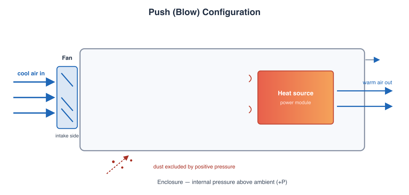
How it works: An electronics cooling fan is mounted on the intake side of the enclosure. Cool ambient air is pushed directly onto the heat-generating components.

Advantages:

  • Outlet air directs straight at the target component — highest local velocity and pressure, useful when one module dominates the heat budget.
  • Positive system pressure prevents dust from entering through enclosure gaps and seams — a key benefit for outdoor enclosure cooling, desert deployment, and shipboard cabinets where salt and sand are present.
  • The fan operates in cool ambient air, extending bearing and motor lifetime.
  • A high airflow dc fan in push configuration can compensate for reduced air density at altitude.

Disadvantages:

  • Airflow velocity is uneven — corners and far edges receive less cooling, with possible dead zones.
  • Recirculation zones can form behind large components if intake geometry is poorly designed.
  • Intake air passes through the fan motor before reaching components, slightly warming the air.
Push blow configuration diagram showing fan on intake side directing concentrated airflow at a heat source inside an enclosure with positive pressure excluding dust
Push (blow) configuration: the fan mounts on the intake side and directs a concentrated jet at the heat source. Positive internal pressure keeps dust out through unsealed paths.

Pull Configuration (Exhaust)

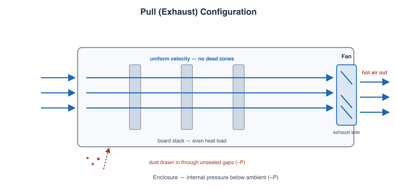
How it works: An electronics cooling fan is mounted on the exhaust side of the enclosure. Hot air is drawn away from components and expelled outside.

Advantages:

  • Uniform airflow velocity across the entire enclosure cross-section.
  • No dead zones — air is drawn from all directions toward the exhaust point.
  • Superior performance in high system impedance applications (dense PCB stacks, filter banks) — pull is the conventional choice when a high static pressure dc fan or a centrifugal blower is needed to overcome flow resistance.
  • Heat is extracted at the exhaust, preventing hot-air recirculation within the enclosure.

Disadvantages:

  • Negative system pressure draws dust and contaminants in through any unsealed gap — this is the principal risk for cabinet cooling fans deployed in dusty or sandy environments.
  • The fan operates in heated exhaust air, reducing bearing and motor lifetime.
  • Lower local velocity at any single component compared to a targeted push configuration.
Pull exhaust configuration diagram showing fan on exhaust side drawing uniform airflow across a board stack with negative pressure drawing dust in through gaps
Pull (exhaust) configuration: the fan mounts on the exhaust side and draws uniform airflow across the board stack. Negative internal pressure pulls dust in through every unsealed gap.

Push-Pull (Combined) Configuration

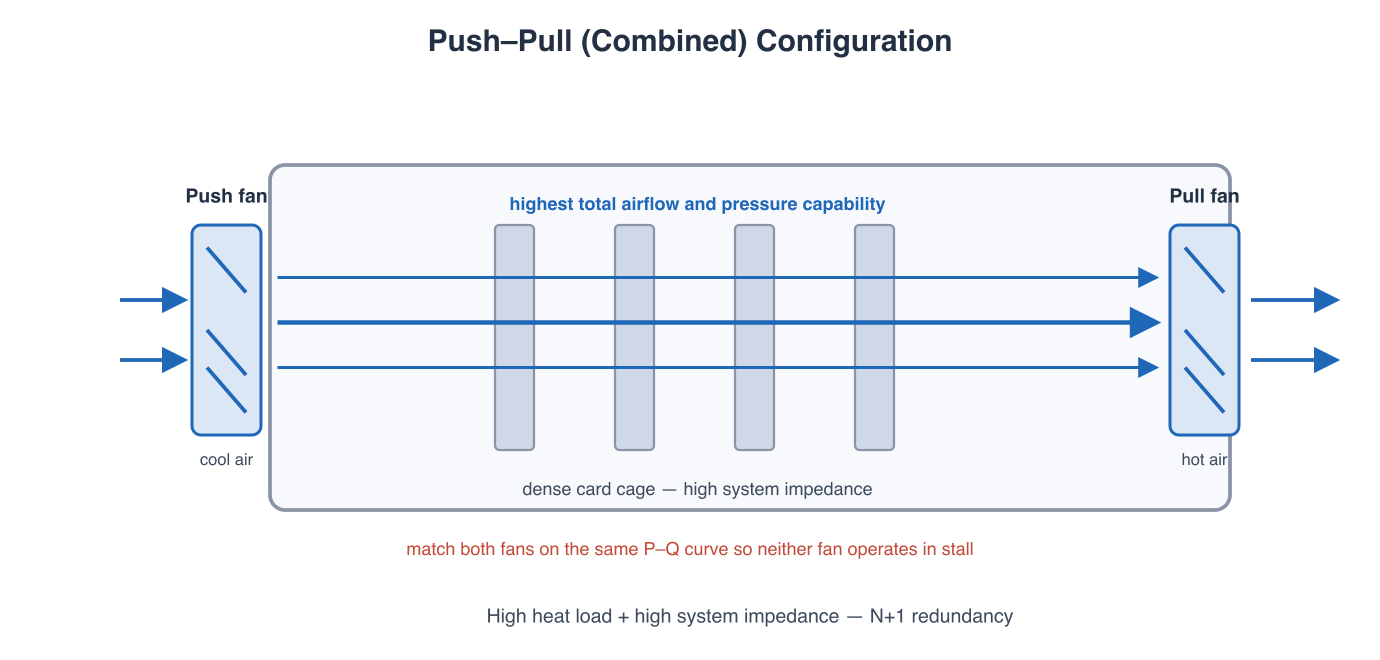
When to use: High total heat load combined with high system impedance — for example, a dense card cage with 10+ boards in a sealed military enclosure. One fan pushes cool air in; a second fan pulls hot air out.

Advantages:

  • Combines positive intake pressure with uniform exhaust flow.
  • Provides N+1 redundancy — if one fan fails, the other maintains partial airflow.
  • Highest total airflow and pressure capability of any single configuration.

Disadvantages:

  • Higher cost, power consumption, and acoustic noise.
  • Requires additional mounting depth and careful balancing of fan curves to avoid one fan fighting the other — compare both fans on the same dc fan airflow curve before pairing.
Combined push-pull configuration diagram with push fan on intake, pull fan on exhaust, and dense card cage between them
Push-pull combined configuration for high heat load with high system impedance. Both fans must be matched on the same P-Q curve so neither operates in stall.

Installation Spacing Rules

Regardless of configuration, observe these minimum spacing rules to avoid airflow starvation. These limits apply to any cabinet cooling fan or electronics cooling fan installation, from a 40 mm blower to a large DC cooling fan in a 200 mm frame.

Parameter Minimum Clearance
Fan-to-board distance (push)≥ 2U (recommend 2× fan thickness)
Fan-to-board distance (pull)≥ 1U (recommend 1× fan thickness)
Intake / exhaust clearance≥ 1U minimum, 2U recommended
Exhaust-to-wall distance≥ 35% of fan diameter
Intake-to-wall distance≥ 100% of fan diameter (ideal: 1–1.5×)

In installation reviews, the most frequent error we see is a pull fan mounted flush against a cabinet wall: the measured airflow drops well below the datasheet value, the fan works harder against its own exhaust reflection, and the extra noise is blamed on the fan instead of the mounting. The fix costs nothing — move the fan one diameter away from the wall. Push configurations require more fan-to-board spacing because the concentrated jet needs room to spread; pull configurations tolerate closer spacing because the suction field is omnidirectional. Use the selected model's airflow vs static pressure (P-Q) data to verify that the available pressure head still meets the system impedance at the planned distance.

Decision Framework: How to Choose

If your system has… Choose Reason
One dominant heat source (power amp, transmitter, avionics power module)PushDirect high-velocity airflow onto the hot spot
Multiple boards with even heat distributionPullUniform velocity, no dead zones across the card cage
Dusty or sandy environment (desert, field deploy, outdoor enclosure cooling)PushPositive pressure keeps dust out of enclosure gaps
Dense board stack (high system impedance)PullHigher static pressure capability overcomes flow resistance
Sealed enclosure with EMI gasketsPushMaintains positive pressure; gaskets seal better under pressure
Very high heat load + high impedancePush-PullMaximizes airflow and provides redundancy
High altitude or UAV installationPush (high static pressure dc fan)Compensates for reduced air density with concentrated jet

Frequently Asked Questions

Q: Can I mix push and pull fans in the same enclosure?

A: Yes — this is the push-pull configuration. It is the best option when heat load and system impedance are both high. In a series push-pull layout both fans pass the same volumetric airflow (flow continuity applies), so the split is in static-pressure duty rather than flow: engineering practice is for the intake (push) fan to handle slightly more than half. Ensure both fans have similar airflow vs static pressure curves so neither operates in stall.

Q: Does push configuration always provide better dust protection?

A: Only if the enclosure is well-sealed. Positive pressure is effective at repelling dust only when all gaps and seams are gasketed. If the enclosure has large unsealed openings, positive pressure simply forces air (and dust) out through those paths without preventing ingress at the intake.

Q: How does altitude affect the push vs. pull decision?

A: At altitude, air density drops, reducing both the fan's pressure capability and the convective heat transfer coefficient. Push configurations are generally preferred at altitude because the concentrated, higher-velocity jet compensates for lower air mass. Pull configurations may struggle to maintain adequate airflow through dense board stacks at reduced density. For UAV cooling fans and avionics bay cooling fans, a high static pressure dc fan is often required to maintain rated airflow at operating altitude.

Q: How to read a fan curve for this decision?

A: The dc fan airflow curve plots airflow (CFM or m³/h) against static pressure (mmH₂O or Pa). The operating point is the intersection of the fan curve and the system impedance curve. For pull configurations in high-impedance enclosures, the operating point must remain on the stable portion of the curve. Plot the selected model's airflow vs static pressure data against your system impedance curve to confirm the operating point.

Q: Should I use an axial fan or a blower in a high-impedance enclosure?

A: As a rule, axial fans — including vane axial designs with guide vanes — deliver higher free-air airflow at lower pressure, while a brushless DC blower or centrifugal blower holds its pressure capability better against dense stacks and filters. If the system impedance curve crosses the axial fan's curve near the stall region, move to a blower or re-plan the configuration rather than accepting an unstable operating point.


Related Articles

Perseus electronics cooling fans support push, pull, and combined push-pull configurations for avionics cooling fans, military vehicle cooling fans, outdoor enclosure cooling fans, and shipboard cabinets. As a high static pressure fan supplier with model-specific fan airflow vs static pressure data, we provide the airflow, pressure, noise, and qualification evidence required for defense, aerospace, and industrial programs. In retrofit programs — including legacy cooling fan cross-reference and form-fit-function replacement reviews where the enclosure geometry is already fixed — send us the mounting footprint and available depth, and we will confirm the workable configuration and match the fan to it. For configuration review and fan curve matching, contact our engineering team.

Technical basis: Fan affinity laws and Perseus airflow-configuration installation practice. This note explains configuration trade-offs and does not assign a universal airflow design to every enclosure. Confirm the selection against the specific enclosure geometry, system impedance, altitude, and qualification requirements. Reviewed August 2026.

Written By

Perseus product image

Dr. Du

Dr. Du is a thermal engineering designer at Perseus, specializing in forced-air cooling design and high-static-pressure DC fan selection for military and defense electronics. He leads airflow configuration and fan curve optimization reviews for rugged cooling applications.