
RFQ Request a Quote
Home
Expand
Technical Resources
Expand
Technical Notes

Vibration Isolation for Military Electronics: A Selection Guide

September 4, 2026 Author:Dr. Du

TL;DR

Defense vibration isolation for military electronics is the discipline that decides whether the same black box passes or fails its qualification test. A line-replaceable unit (LRU) bolted hard to an armored-vehicle bulkhead sees the full platform vibration spectrum; the same unit sitting on isolators sees a fraction of it above the isolator's natural frequency - and up to several times more of it at resonance. Defense vibration isolation is therefore not an accessory decision made after the thermal and electrical design; it is a test-planning decision that changes the excitation the equipment is actually qualified against.

This engineering guide covers the three specification decisions that matter: which isolator architecture to select (adaptive metal damping, friction damping, high-damping silicone mounts, or integrated module isolation), how to define the mounting interface so the isolation is not short-circuited by the installation, and how to handle the difference between hard-mounted and isolated qualification testing. For the product context, see the Perseus vibration isolators product page, which covers adaptive and silicone isolators from 0.05 kg to 200 kg per unit by configuration.

Three decisions decide whether an isolated payload passes its qualification test. First, the architecture: adaptive metal and friction dampers for controlled resonance behavior on well-characterized platforms, high-damping silicone where a compact part must attenuate a broadband spectrum. Second, the natural-frequency target: below half the lowest disturbing frequency, so the system stays inside the isolation region above the √2 crossover. Third, the mounting interface: shoulder bushings, clearance at full deflection, flexible cable runs, and a grounding strap, so the installation does not short-circuit the mount. Get those three right and the test-planning consequence follows - a hard-mounted unit is qualified against the full platform spectrum, an isolated unit against amplified response at resonance plus the attenuated region above it, with method, category, curve, and acceptance criteria written into the program test plan before the first shake.
Why Isolation Changes the Qualification Problem

An isolator does not simply "reduce vibration." It reshapes what reaches the equipment - attenuated above the mount's natural frequency, amplified near it - and the qualification test must match that reshaped input, not the raw platform spectrum.

Mounting condition What reaches the equipment Where failures concentrate
Hard-mounted (direct to structure)Full platform spectrum up to the structure resonanceHigh-frequency vibration fatigue of PCBs, connectors, and small components
Isolated (through isolators)Amplified response near the isolator resonance; attenuated response above about 1.4x the natural frequencyResonance amplification during start-stop and shock; isolator fatigue and creep over life

A frequent field failure mode is a system that passed its hard-mounted component test but fails in service, or the reverse: a system that passes its isolated-system test because the isolator attenuates the test input, only to resonate in service at a frequency the test never excited. Both cases trace back to the same error - defining the test without first defining the mounting condition. The failure-mode context for electronic equipment is covered in the Perseus technical note on cooling fan and electronics failure modes, where vibration-driven connector and PCB fatigue appears consistently among fielded causes.

Isolation Physics in One Page

Every isolator selection reduces to one curve: the transmissibility of the isolator-payload system - the ratio of the vibration reaching the payload to the vibration applied at the base. For a single-degree-of-freedom system the curve divides into three regions, and each region asks the designer a different question.

  • Resonance region (excitation near the isolator natural frequency fn). The isolator amplifies the input. The amplification factor is approximately 1 / (2 × damping ratio), so a lightly damped metal isolator can multiply the input several times at resonance. Every payload passes through this region during start-stop and shock events, which is why damping at resonance matters as much as stiffness. And if the dominant platform excitation lands at or near fn, isolation makes the response worse, not better - the fix is to re-target the natural frequency or add damping, never to assume the mount protects the payload there.

  • Isolation region (excitation above about 1.4 × fn, the √2 crossover). Transmission falls with frequency ratio, and this is where the isolator does its work. Higher frequencies are attenuated more, which is why isolators protect against the high-frequency vibration that fatigues PCBs and connectors.

  • Static region (excitation well below fn). The isolator behaves nearly rigidly, and low-frequency platform motion reaches the payload essentially unchanged. An isolator cannot help with a disturbance below its natural frequency; the response is to lower the natural frequency, which usually means a softer mount and a larger static deflection envelope.

The practical design rule used across the Perseus isolator range: target an isolator natural frequency below half the lowest disturbing frequency so the system operates comfortably inside the isolation region for the dominant excitation, with damping sized to keep the resonance amplification within the payload's shock-and-vibration capability.

Isolator Types: What the Four Architectures Actually Do

The Perseus isolator family covers four architectures, and each trades resonance management against broadband attenuation differently:

Architecture How it manages vibration Best fit
Adaptive metal dampersMetal stiffness with damping that adapts to the resonance zone, preserving isolation outside resonanceAvionics and shipboard electronics with well-defined platform spectra
Friction dampingFriction interfaces dissipate energy at resonance without large static deflectionGround mobile and vehicle electronics with frequent shock events
High-damping silicone mountsElastomeric material gives broadband attenuation and weathering resistance in a compact partCompact chassis, lightweight payloads, and guidance modules
Integrated module isolationChassis mounting and vibration protection combined in one structural assemblySpace-constrained airborne and missile payloads where SWaP is critical

The selection logic is a three-way trade. Metal and friction architectures give controlled resonance behavior with a defined load path; silicone gives broadband attenuation and environmental robustness but with a softer, temperature-sensitive stiffness; integrated assemblies trade design freedom for packaging efficiency. Load cases are reviewed from 0.05 kg up to 200 kg per unit by configuration, which spans everything from a small guidance module to a heavy shipboard rack.

Sizing the Isolator: Load, Natural Frequency, and Deflection

Isolators are tuned around two numbers: the natural frequency of the isolator-payload system and the load each isolator carries. The classic failure is an isolator selected by envelope size rather than by deflection, so the payload sits at the edge of the mount's rated travel instead of near its intended operating deflection.

  1. Define the load per isolator, not the total payload mass. Divide the payload weight by the isolator count, then correct for the center of gravity: if the payload CG is offset, the corner isolators carry unequal shares and the stiffest-loaded corner sets the required load rating. Add the platform's static acceleration and a safety factor before matching the mount's rated load range.

  2. Set the natural-frequency target from the disturbance, then select stiffness. Target a system natural frequency below half the lowest disturbing frequency of the platform (propeller or rotor fundamental, track bounce, or the dominant random-vibration band). The isolator data sheet maps natural frequency to load and deflection, so the stiffness choice follows from the frequency target and the per-isolator load.

  3. Verify the deflection envelope. A softer isolator (lower natural frequency) deflects more under the payload and under shock. The mounting design must allow that deflection without the payload bottoming against structure, and the travel limits must be included in the envelope check.

  4. Check damping at resonance. The same payload that is well isolated at cruise still passes through the isolator resonance at engine start, at landing, and under shock. Confirm the architecture's damping ratio keeps the resonance amplification inside the payload's capability for the shock events in the platform profile.

The Mounting Interface: Installation Rules That Keep the Isolation Real

An isolator is only as good as its installation. When a field report says "the isolators do not seem to work," the isolator is rarely the problem - the installation is. Some detail of the mounting short-circuits the isolation path, so vibration travels around the mount instead of through it. Five rules catch most of those details.

  • Use the specified shoulder bushings and washers on every fastener. A bolt torqued hard enough to compress the isolator solid creates a metal-to-metal path that defeats the mount. The fastener hardware controls the load path and must match the isolator data sheet.

  • Preserve clearance around the isolator and the payload. Any structure touching the isolated payload - a cable bundle, a conduit, a stiff connector, or the enclosure itself - becomes a parallel path that transmits vibration directly. Check clearance at the extremes of the deflection envelope, not only at rest.

  • Keep cable and waveguide routing flexible across the isolation boundary. The classic overlooked path: a cable bundle dressed tight across the interface turns a soft mount into a hard one, feeding vibration and shock straight into the payload. Flexible leads with a service loop are the standard practice.

  • Restore the electrical bond across the interface. Many isolators are electrically insulating, so an isolated chassis can lose its grounding bond to the aircraft or vehicle structure. A braided grounding strap across the isolation interface restores the bond and prevents EMC and lightning-protection problems, while still flexing with the deflection envelope.

  • Pair chassis isolation with board-level retention. Isolators protect the chassis from external shock and vibration, but they do not stop an inserted board from resonating inside the chassis. Wedge locks and card retainers prevent board-level resonance, and rugged systems normally need both working together - the two roles are complementary rather than interchangeable.

Hard-Mounted vs Isolated Qualification Testing

The difference between hard-mounted and isolated testing is the difference between qualifying the equipment against the platform spectrum and qualifying the equipment against the isolated interface response. Both are legitimate; they answer different questions.

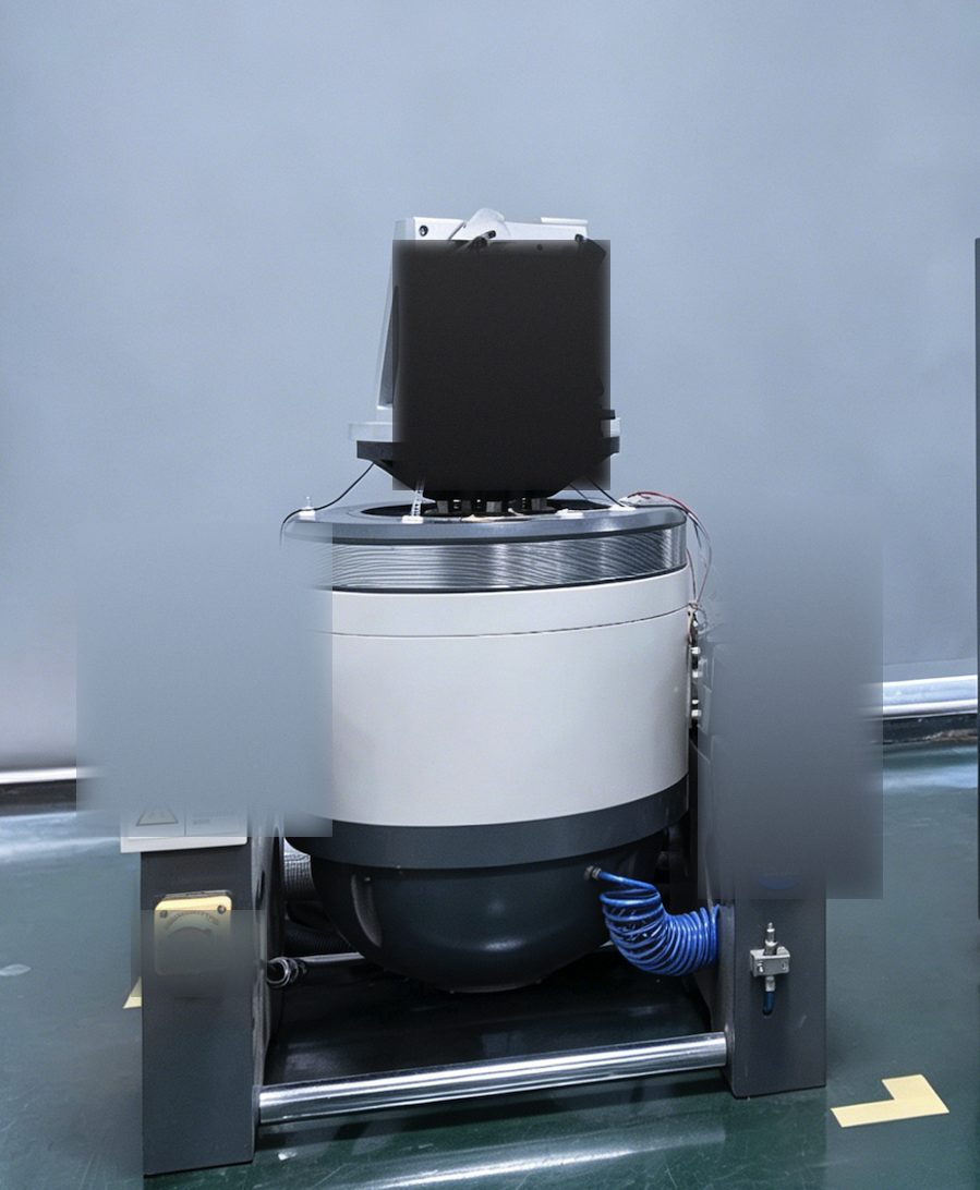
Electrodynamic vibration shaker used for Perseus qualification testing, with a black test fixture mounted on the armature and a steel support frame
The electrodynamic shaker used for Perseus qualification testing. The unit under test is fixtured to the table; in an isolated-system test the payload mounts through its isolators, so one run exercises both the amplified response at resonance and the attenuated high-frequency region above it.

Hard-mounted testing applies the platform's vibration profile directly to the equipment. It is the appropriate qualification for equipment that will be bolted directly to structure, and it is the conservative check because the equipment must survive the full spectrum. The failure mode it exposes is high-frequency fatigue of PCBs, connectors, and small parts.

Isolated-system testing applies the platform profile to the isolated assembly as a whole. The isolators attenuate the high-frequency content reaching the payload and amplify the response near resonance, so the test exercises the resonance behavior and the attenuated high-frequency region together. The isolators themselves are part of the article under test and are qualified to the same shock and random vibration plan, with method, category, curve, and acceptance criteria defined in the program test plan.

The tailoring rule. When an LRU will be isolated in service, the test plan should reflect the installed condition rather than blindly applying the raw platform spectrum to the bare unit. MIL-STD-810H Method 514.8 is written around test tailoring, and the same logic governs the shock profile under Method 516.8: the excitation at the equipment interface is the quantity that matters. The evidence framework for defining and documenting this is the same one used across Perseus environmental qualification work and is described in the technical note on military equipment environmental qualification. Whatever condition is chosen, it must be stated in the test plan before testing, with the acceptance criteria defined up front.

One caution applies to both approaches. Testing an isolated assembly with the isolators at their softest, or at a temperature outside the elastomer's rated range, changes the resonance frequency and can hide a real resonance problem. Temperature affects elastomeric stiffness significantly, so isolated-system testing should bracket the operating temperature range or the natural-frequency shift must be accounted for in the analysis.

Random vibration qualification test data: acceleration power spectral density in g2/Hz versus frequency on log-log axes, comparing two overall RMS levels
Random vibration test data from Perseus qualification testing, plotted as acceleration power spectral density (g²/Hz) against frequency on log-log axes, comparing two overall RMS levels. Spectra of this kind are what the vibration input profile in the six integration data points refers to - and what both the hard-mounted unit and the isolated assembly must be qualified against.

Environment and Materials Review

Isolators are life-limited elastomeric and metallic components, and their environment is part of their specification. Three exposure classes dominate in defense service:

  • Temperature. Perseus isolator configurations cover -55 °C to +85 °C by configuration. Elastomer stiffness changes with temperature, which shifts the natural frequency, so the operating range must be stated with the frequency analysis rather than after it.

  • Salt fog, humidity, and ozone. Shipboard and coastal installations expose silicone and metal hardware to salt-laden air; ozone attacks elastomers over time. The Perseus review practice is that salt fog, humidity, ozone, and thermal cycling requirements should be confirmed by platform exposure and the test plan, then mapped to the selected material system.

  • Fluid exposure. Aviation oils, hydraulic fluids, and cleaning solvents degrade unprotected elastomers. Where fluid exposure is expected, the compound and any protective coating must be selected for it, and the isolator data sheet should state the fluids the material has been reviewed against.

Creep and set are the long-term failure modes of an isolator: over years of static load, an elastomer compresses and the payload sinks, changing the natural frequency and eventually bottoming the mount. The design-in review should include the service-life expectation and the deflection margin available before the mount reaches its travel limit.

Perseus Vibration Isolators

The Perseus vibration isolators product range is the reference for the concepts in this guide: adaptive metal dampers and friction damping for resonance management, high-damping silicone mounts for compact broadband attenuation, and integrated module isolation assemblies for SWaP-constrained payloads. Load cases are reviewed from 0.05 kg up to 200 kg per unit by configuration, and the operating range covers -55 °C to +85 °C by configuration.

Four typical applications map onto the architecture table above: airborne avionics and sensor payloads (mission computers, sensor modules, avionics racks exposed to vibration-driven connector and PCB fatigue); shipboard radar and communication electronics (continuous low-frequency vibration plus salt-laden environment); ground mobile electronics (vehicle-mounted equipment and tactical shelters); and compact payload and guidance modules (integrated isolation where space is the constraint).

Selection starts from six integration data points that should be available before any isolator is chosen or any custom review begins: mounting envelope, static load per isolator, the vibration input profile (random, sine, shock, and resonance concerns), the target natural frequency, the center of gravity and mounting orientation, and the environmental exposure. The Perseus engineering team supports the review with the load, frequency, and environmental matching, and with the qualification planning against defense-grade shock and random vibration profiles where method, category, curve, and acceptance criteria are defined in the program test plan.

Frequently Asked Questions

Q1. When does a military electronics chassis actually need vibration isolators?

When the platform excitation at the equipment interface exceeds what the equipment can survive, or when the equipment's own vibration must not reach a sensitive neighbor (for example, a fan or a motor near a precision sensor). The decision is made by comparing the platform profile at the mounting location with the equipment's hard-mounted vibration capability; if the margin is thin, isolation is the lower-risk choice.

Q2. How do I pick the right isolator for my system weight?

Match the mount's rated load range to the actual installed weight, so the system sits near its intended operating deflection rather than at the edge of the rated travel. An isolator chosen by envelope size alone almost always runs at the wrong deflection point. This is the rule stated in the Perseus isolator selection guide.

Q3. Should the natural frequency be above or below the disturbance frequency?

Below it - the isolator only attenuates above about 1.4 times its natural frequency. The working rule is to target a natural frequency below half the lowest disturbing frequency, with damping sized to control the resonance amplification that the payload passes through during start-stop and shock.

Q4. What is the difference between testing hard-mounted and testing on isolators?

Hard-mounted testing applies the full platform spectrum to the equipment and exposes high-frequency fatigue. Isolated-system testing applies the platform profile to the isolator-payload assembly, exercising the resonance amplification and the attenuated high-frequency region together. The condition must be chosen and stated in the test plan before testing, because the acceptance criteria depend on it.

Q5. Metal damper or silicone mount?

Metal or friction architectures for heavier payloads on well-characterized platforms; high-damping silicone for lightweight payloads that need broadband attenuation in a compact part. The deciding factors are the platform profile, the payload sensitivity, and the load per isolator.

Q6. Do I also need locking strips or card retainers?

Yes, for a different reason. Vibration isolators protect the chassis from external shocks and vibration, while wedge locks and card retainers prevent inserted boards from resonating under vibration. Rugged systems normally need both working together - they are complementary, not interchangeable.

Q7. Will an insulating isolator break my grounding?

It can. Many isolators are electrically insulating, so an isolated chassis may lose its bond to structure. A braided grounding strap across the isolation interface restores the electrical bond and flexes with the deflection envelope, preserving both the isolation and the EMC and lightning-protection performance.

Conclusion

Defense vibration isolation is a test-planning discipline as much as a hardware decision. Selecting the isolator architecture, targeting the natural frequency below the disturbing band, and defining the mounting interface so the isolation path stays real are the three decisions that make an isolated system work. The fourth - stating whether the equipment is qualified hard-mounted or as an isolated assembly - is the one that connects the hardware to the program test plan and to the acceptance criteria. Perseus vibration isolators cover the range from 0.05 kg guidance modules to 200 kg shipboard racks, with adaptive metal, friction, and high-damping silicone architectures, and the engineering team supports the load, frequency, environmental, and qualification review. Contact the engineering team to start an isolation specification.

Written By

Perseus product image

Dr. Du

Dr. Du is a thermal engineering designer at Perseus, specializing in forced-air cooling design and high-static-pressure DC fan selection for military and defense electronics. He leads airflow configuration and fan curve optimization reviews for rugged cooling applications.