RFQ Request a Quote
Home
Expand
Technical Resources
Expand
Technical Notes

Naval Cooling Fans: Specifying for Vibration, Shock and Salt Fog on Shipboard Electronics

November 19, 2026 Author:Dr. Du

Key Takeaways

A naval cooling fan is not an avionics fan with a salt-spray test added. The fan on a shipboard cabinet is asked to move air while it is itself being shaken by the propulsion train, struck by weapon shock through the deck, wetted by salt-laden air for years, and powered from a 400 Hz bus or a 28 V DC battery string that sags and spikes. Each of those conditions attacks a different part of the fan - the blade root, the bearing, the winding, the Hall sensor, the lead exit. A fan that survives all four separately may still fail when they arrive together, because vibration opens a sealing path that salt fog then enters.

This guide treats the fan as the subject, not the cabinet around it. It covers what MIL-STD-167-1A and MIL-S-901 actually ask of the fan, how mounting and isolation change the fan's own operating point, why a sealed IP67 fan and a moving-air fan are in conflict by design, and how to size airflow margin when the deck is never still. It closes with the evidence list to request before a fan is written into a shipboard build.

The practical rules: keep the fan's natural frequency and the mount's natural frequency apart; target airflow margin against a blocked or salt-fouled path, not a clean one; treat the fan as an internal excitation source under MIL-STD-167-1A Type II, not only as a victim; and confirm that the IP rating was qualified on the same frame, bearing and lead-exit configuration that will ship.

Why a Shipboard Fan Is a Different Specification Problem

On an aircraft the fan is designed against a finite mission profile: takeoff, cruise, landing, and a defined number of flight hours. On a naval platform - a ship or a submarine - the fan is designed against a continuous duty cycle that runs for the life of the hull. The cabinet is never powered down for the season, the deck is never still, and the air is never clean. That difference in duty cycle, not any single shock number, is what makes naval fan specification its own discipline.

Three consequences follow, and they are the reason a fan selected from an airborne catalog usually underperforms at sea.

The excitation is continuous and low-frequency. Propeller blade rate and diesel-generator harmonics sit in the same band where a fan's own rotor dynamics live. This is not a high-frequency buzz that a stiff mount filters out; it is a slow, large-amplitude motion that the whole fan structure follows. Blade roots, lead exits, and connector latches accumulate fatigue over months rather than cycles.

The failure mode is usually corrosion-assisted, not purely mechanical. A bearing that would run its rated life in dry air fails early when the lubricant is contaminated by salt aerosol drawn through a degraded seal. A fan that passes vibration on a shaker and passes salt fog as a static specimen can still fail both when the vibration test is run first and the seal no longer sits flat.

The electrical environment is not a laboratory supply. Ship's power includes transfer switching, generator load steps, and long cable runs. The fan sees voltage transients and a source impedance that a bench supply never reproduces. A fan specified only at nominal voltage and nominal current can start unreliably on a real bus.

None of this argues for a special "marine fan." It argues for specifying the fan against the four loads explicitly, in the order they dominate the design - which is the subject of the next section.

The Four Loads a Naval Fan Actually Sees

Shipboard environmental specifications are usually written for the cabinet, then inherited by the fan by default. That inheritance loses the detail that matters, because the fan is the one component with a rotating cantilever structure, a precision bearing, and an air path that must stay open to atmosphere. The table below separates the four loads and identifies what each one attacks.

Load Typical origin What it attacks in the fan Specification lever
Continuous vibration Propeller blade rate, diesel-generator harmonics, sea state transmitted through the hull Blade root fatigue, bearing race fretting, lead-exit cracking, fastener loosening MIL-STD-167-1A Type I endurance at the identified resonance; mount selection
Shock Weapon discharge, underwater explosion, heavy sea slam Rotor-to-stator contact, blade breakage, bearing brinelling, stator deformation MIL-S-901 grade matched to equipment weight and mounting location
Salt fog, humidity, immersion Spray on deck, condensation in compartments, washdown, temporary flooding Bearing lubricant, stator insulation, Hall sensor, connector pins, housing finish IP rating qualified on the shipping configuration; salt spray hours; material and finish review
Electrical quality Generator load steps, power transfer, long cable runs, 400 Hz bus Drive-stage margin, inrush behavior, speed stability, controller lockout MIL-STD-704 transient withstand, peak-current margin, 400 Hz motor design

Two observations from this table drive most of the decisions later in this guide. First, three of the four loads are mechanical or chemical, so the fan's mechanical architecture - bearing type, blade attachment, housing sealing method - carries more of the survival burden than the motor specification does. Second, the electrical load is the easiest to underestimate: it does not degrade the fan gradually, it prevents it from starting.

The 400 Hz case deserves a note because it is often treated as a voltage question when it is a magnetic design question. A motor wound for 50/60 Hz operation and then run on 400 Hz has the wrong impedance and the wrong flux density; the result is overheating, acoustic noise, and in some cases a rotor that will not synchronize to the supply. A fan built for military 400 Hz power is a different magnetic design, not a different nameplate.

MIL-STD-167-1A and MIL-S-901: What They Ask of the Fan Itself

The two standards that govern naval mechanical environment are frequently quoted together and understood separately, which is a mistake. They test different things, at different amplitudes, over different durations, and a fan can pass one while failing the other.

MIL-STD-167-1A covers vibration and defines two excitation types. Type I is environmental vibration: the motion arriving from the ship - propulsion machinery, propeller, and sea state transmitted through the hull. Type II is internally excited vibration: motion generated by equipment mounted on the same structure, including rotating machinery such as fans and pumps. Most fan specifications address only Type I, treating the fan as a passive victim. That omission matters on a naval cabinet, because a fan is a rotating mass with residual unbalance, and it excites the very structure it is bolted to. In a cabinet with several fans, the second and third fan inherit a structure already moving.

The test sequence itself is the part that is most often misunderstood. A Type I qualification is not a single sweep. It begins with an exploratory sweep that searches for resonances in the mounted configuration, then applies endurance testing at the resonances that were found. Passing the exploratory sweep alone proves only that the fan did not fail immediately; it says nothing about the fatigue that accumulates at a resonance the fan will sit on for years. When a supplier reports "passed MIL-STD-167-1A," the question to ask is which resonances were identified and at what duration they were endurance-tested.

MIL-S-901 covers shock and is graded, not pass/fail. The grade - lightweight, medium weight, or heavyweight - is determined by the weight of the equipment and by where it is mounted on the ship, not selected by preference. The test applies a defined shock input through a floating shock platform or an equivalent hammer blow, and the acceptance criterion is usually continued operation, not merely freedom from structural failure. For a fan, "continued operation" is a demanding criterion: the rotor must not contact the stator, the bearing must not brinell, and the fan must restart and hold speed afterwards.

The interaction between the two standards is where fan design is actually decided. A mounting arrangement that is compliant for shock - stiff, with limited travel - transmits more high-frequency vibration into the fan. A mounting arrangement that is soft enough to attenuate vibration will deflect further under shock, and may bottom out. The fan mounting therefore has to be designed for both cases at once, with a deflection margin that satisfies shock travel and a natural frequency that stays below the vibration band. The mounting section below covers how that trade is made in practice.

Selecting the Fan: Airflow Margin and the Stall Boundary

Airflow selection on a naval platform fails in a specific and predictable way: the fan is sized against a clean, idealized air path, and then installed behind a filter, a louvre, an EMI screen, and a cable bundle. The system resistance rises, the operating point slides up the pressure curve toward lower flow, and the cabinet runs hotter than the thermal model predicted. The fan did not underperform; it was specified against the wrong system curve.

Start from the installed system curve, not the free-air rating. The fan's own characteristic curve and the system's resistance curve intersect at the operating point. Everything that adds resistance - inlet filter, outlet louvre, honeycomb EMI screen, duct bends, dense card cages - moves that intersection. A specification that quotes only maximum free-air airflow has not defined the operating point at all.

Keep the operating point away from the stall region. At high pressure and low flow, an axial fan enters an unstable condition in which the flow separates from part of the blade span and a rotating stall cell forms. That cell is not just an efficiency loss: each blade passes through it once per revolution and receives an excitation pulse. The result is blade resonance, root cracking, and accelerated bearing wear. On a shipboard cabinet, where the fan is already being excited by the hull, adding a stall-driven excitation at the blade passing frequency is a compounding risk. The selection rule is to keep the operating point on the stable part of the curve with margin to the left-hand region, and to confirm the installed resistance at end-of-life (fouled filter, partially blocked screen), not only at commissioning.

Use series and parallel combinations deliberately. Two identical fans in series do not increase free-air flow; they approximately double the static pressure capability, which is the right choice for a high-resistance path. Two fans in parallel do not increase pressure; they approximately double the flow at a given pressure, which is the right choice for a low-resistance path that needs volume. Applying the wrong combination produces a cabinet that still overheats while consuming twice the power.

Respect the inlet and outlet geometry. Fans need clearance to draw air evenly. A practical rule is to keep the fan at least one fan thickness away from the board or surface it cools; for a blowing arrangement, one rack unit of clearance is the minimum and two is preferable, while for an exhaust arrangement one rack unit is generally sufficient. Abrupt expansion, abrupt contraction, and sharp turns at the inlet all cost pressure that the fan has to make up. Where a turn is unavoidable, a turning vane recovers more pressure than an open corner, and downstream cross-sections should be larger than upstream ones rather than smaller.

On a naval cabinet these geometry rules interact with mounting hardware. An isolator adds height under the fan flange, which changes the clearance to the board above it and can shorten the effective inlet path. That is a real airflow cost, and it should be included in the thermal model before the mount is chosen, not discovered during sea trials.

Mounting: Where the Vibration Path Is Actually Broken

There are two distinct reasons to isolate a shipboard fan, and confusing them leads to the wrong hardware. The first is to protect the fan from the ship: reduce the motion arriving at the blade root and bearing. The second is to protect the cabinet from the fan: stop rotor unbalance from exciting a structure that carries sensitive electronics. The first calls for a mount sized to the fan's mass and the platform spectrum. The second calls for a mount that decouples the fan's running speed from the panel's structural modes. A single mount cannot always do both, and on small fans the constraint becomes severe.

Small fans are the hard case. A 30 mm to 80 mm fan weighs little, sometimes only a few hundred grams. Isolators are rated by load, and a mount designed for a 5 kg payload will barely deflect under a 0.3 kg fan - which means the mount acts almost rigidly and provides no isolation at all, while adding height and a failure point. This is why isolator ranges extend down to very light loads: the Perseus isolator range covers 0.05 kg to 25 kg per unit by part number. Selecting by envelope size instead of by load is the most common error in fan isolation, and it is invisible until a resonance appears.

Keep the two natural frequencies apart. The mount has a natural frequency determined by its stiffness and the supported mass; the fan has rotor and structural dynamics of its own. The mount only attenuates above roughly 1.4 times its own natural frequency, so the working target is a mount natural frequency below half of the lowest significant disturbing frequency. The isolator families differ here: the adaptive metal dampers sit in the 12 Hz to 35 Hz range depending on part number, the friction-damped family in the 12 Hz to 22 Hz range, and the silicone family at or below 50 Hz. For a propeller blade rate near 10 Hz, only the lower-frequency families give real attenuation; a 50 Hz silicone mount is being used as a compliant spacer rather than as an isolator.

Do not let the installation short-circuit the mount. Isolation is defeated by anything that bridges the isolated body to the structure: a rigid cable bundle, a grounding strap with no slack, a duct clamped at both ends, a fastener torqued against the housing instead of the mount. Each of these is common in shipboard cabinets, and each one turns a correctly specified isolator into decoration. The design review should trace every connection to the fan and confirm that it accommodates the full deflection travel in all three axes.

Check the deflection against the available space. A mount that attenuates well at running speed may exceed its travel under shock and bottom out, at which point the shock load goes straight into the fan frame. The practical review is to compare the calculated shock deflection with the mount's rated travel and with the physical clearance to adjacent structure, then decide whether a different mount or a different fan location is required.

Where the fan and the mount are one assembly. For high-shock locations the more robust answer is a fan module in which the fan, its isolators, and its mounting frame are qualified as a single unit rather than assembled from three separately qualified parts. A module designed this way is characterised for random vibration in the range of 30 g rms, which is a different class of mechanical environment from a stand-alone fan on a bracket, and it removes the interface assumptions that usually break down in integration.

Sealing and Materials: IP67, Salt Fog, and Immersion

A fan is an opening in an otherwise sealed enclosure. That is the central conflict of sealing a fan for the marine environment: the fan must let air through and must keep salt water out. Every sealing decision is a trade against airflow, and the trade has to be made deliberately rather than by choosing the highest IP number available.

IP67 and IP68 mean different things and are not interchangeable. IP67 covers temporary immersion - 1 m of water for 30 minutes under the IEC 60529 definition; IP68 covers continuous immersion at a depth and duration agreed between manufacturer and user. On a shipboard cabinet, the realistic exposure is spray, washdown, and short-term water ingress - an IP67 case. Equipment mounted low on deck or in a compartment with flooding risk may justify IP68, but the configuration that achieves it usually has a different airflow characteristic and should be re-checked against the thermal model. Because both ratings are configuration-dependent, a specification should state the rating per model and per frame size rather than as a product-line claim.

Salt spray duration should match the service interval, not the shortest passing test. Neutral salt fog tested to MIL-STD-810H Method 509 at 96 hours is a common baseline for equipment that will be inspected on a defined interval; acidic salt fog at 192 hours addresses the more aggressive conditions associated with exhaust-affected and industrial atmospheres. Some deck-mounted equipment is specified against substantially longer exposure, including immersion testing measured in hundreds of hours where spray and short-term flooding are both credible. The useful question is not "how many hours did it pass" but "what inspection and replacement interval does that number support on this platform."

The seal is a system, not a gasket. On a fan, the paths that admit water are the flange gasket, the lead exit, the bearing seal, and the gap between the impeller and the housing. A high IP rating achieved by sealing the housing while leaving the lead exit as a potted but mechanically unsupported joint will fail in service: vibration works the joint, salt fog enters the strands, and the failure appears as an open circuit rather than as a water leak. Inside the motor, moisture that enters and then evaporates leaves recrystallized salt on the winding and on the bearing, and the failure presents as a locked rotor at start-up rather than as visible corrosion. Material choices follow the same logic. Silicone and other high-damping elastomers are used in naval mounts partly because they resist weathering and ozone and retain properties over long shelf and service life; housing finishes and fastener plating must be chosen for the same atmosphere rather than for cost.

Corrosion changes the air path. Over a service life, salt deposits build on blade leading edges and on inlet screens, and corrosion products roughen surfaces that were specified as smooth. Both effects reduce flow. A fan specified with zero margin will meet its thermal target on the day it is commissioned and miss it two years later. The margin rules given under Selecting the Fan exist for this reason as much as for filter loading.

Power and Control on the Ship's Bus

The electrical side of a naval fan specification is usually written as a voltage and a current. That is not enough to predict whether the fan will start on a real bus, and starting is where most electrical failures appear.

Rated current is an average, not a peak. A fan is an inductive load, and its current waveform is not sinusoidal: it shows a sawtooth with a superimposed spike as the drive stage switches. The peak current is typically 1.5 to 3 times the average current quoted in a datasheet. A supply sized on average current alone will see over-current protection trip, output voltage droop, hesitant or oscillating start-up, and elevated supply temperature. The specification should carry the peak figure and the supply should be checked against it, not against the nominal.

Transients arrive from outside the fan. Power transfer between generators, load steps from other consumers, and long cable runs all produce voltage excursions at the fan terminals. Fans built for military power buses are expected to ride through defined transient profiles rather than to be protected from them by the system. Where a fan is fed from a converter, the transient withstand of the converter becomes part of the fan's qualification chain and should be stated as such.

Speed control and feedback are part of the thermal design. A PWM input lets the system trade noise and power against temperature, and the aerodynamic relationships are fixed: airflow scales with speed, static pressure with the square of speed, and power with the cube. That cubic relationship is why a modest speed reduction produces a large power and acoustic benefit, and why a control loop that hunts is expensive in both. Speed feedback (FG) and rotation detection (RD) are what allow a failed fan to be identified as failed rather than as an unexplained hot spot; on a shipboard cabinet where several fans serve one enclosure, that distinction shortens fault finding considerably.

Control wiring is an EMC path. The fan's signal ground is the fan's negative terminal, so a control signal referenced to a different ground will carry a potential difference. Long control runs to a fan mounted on an isolated frame are especially exposed: the isolated frame can float, and the control cable becomes the bridge that defeats both the isolation and the shielding. Adding common-mode inductance, transient suppression, and filtering at the control interface, and avoiding direct connection of a microcontroller pin to a fan signal line without protection, are standard practice for this reason. They are also part of what keeps the installation inside the conducted-emission and susceptibility limits of MIL-STD-461, the EMC baseline most shipboard electronics are verified against.

Qualification Evidence: What to Ask For

Shipboard fan procurement goes wrong when the specification asks for standards and the supplier answers with standards. A statement that a fan "meets MIL-STD-810H" is not evidence of anything in particular, because the standard defines hundreds of methods, procedures, and categories, and a fan can meet one while failing another that matters on the platform. The table below converts the requirement into the specific evidence to request.

Requirement Evidence that actually answers it Common weak answer
Vibration endurance MIL-STD-167-1A Type I report naming the resonances found in the mounted configuration and the endurance duration applied at each "Compliant with MIL-STD-167" with no resonance or duration data
Shock MIL-S-901 report stating the grade, the equipment weight and mounting location it applies to, and the post-test operating condition A shock figure quoted without the grade or the mounting basis
Sealing IP test report identifying the exact frame size, bearing type, and lead-exit configuration tested An IP number quoted for a product family rather than a part number
Salt fog Salt fog and humidity test hours, neutral or acidic, and the inspection criteria applied afterwards Hours quoted with no statement of which fog or what was inspected
Temperature Operating and storage range per model, with the cold-start condition stated separately A single range that omits whether starting was tested at the low limit
Electrical Transient withstand profile, peak-to-average current ratio, and the minimum supply capability for reliable start Nominal voltage and nominal current only
Quality system Current AS9100 and ISO 9001 certification covering the manufacturing site that will produce the fans A certificate with no site or scope statement

One further item belongs on the list even though it is not a test: the configuration. On a fan, the tested article and the delivered article must be the same frame, the same bearing system, the same impeller material, and the same lead exit. A qualification report for a 60 mm ball-bearing unit does not transfer to an 80 mm sleeve-bearing variant, and the substitution is easy to make late in a program when a frame size changes. Recording the part number on the report, and holding the supplier to it, prevents most of the surprises that appear at first article inspection.

Perseus Fan Families for Shipboard Electronics

For shipboard electronics cooling, the Perseus small DC fan range covers 30 mm to 80 mm catalog frames in three series placed by nominal band: Minipro at 50 mm and below, Superpro from 51 mm to 70 mm, and Ultrapro across the 71 mm to 91 mm band, which currently ships as 80 mm frames. These are the frames used inside shipboard communication cabinets and console electronics, where the air path is short and the mounting depth is fixed. DC input spans 5 V to 48 V by model, with PWM speed control and FG/RD feedback available, and protection ratings are specified per model as a configuration option rather than as a line-wide claim.

The Perseus large DC fan range covers 92 mm to 240 mm frames in Megapro at 92 mm to 110 mm, Hyperpro at 111 mm to 150 mm, and Archpro at 151 mm and above. These serve the higher-volume cases - radar cabinets, transmitter bays, and equipment rooms where a single fan must hold airflow across a long duct run. Where the enclosure is a sealed cabinet with a heat exchanger, the higher static pressure capability of these frames is what allows the air path to include a folded route and a filter without collapsing the operating point.

The Perseus centrifugal fan range covers 50 mm to 120 mm in Prometheus at 110 mm and below and Atlas at 111 mm and above. Centrifugal impellers hold pressure against restricted paths, which is the situation in shallow console housings and in enclosures where the inlet and outlet cannot be placed on opposite faces. For naval console display cooling, this is often the only frame that fits the available depth while still moving enough air.

The Perseus 400 Hz AC fan range is built for military 400 Hz and 450 Hz buses at 115 V and 208 V, with the Titan series covering 25 mm to 252 mm envelopes. These are wound for 400 Hz operation rather than adapted from 50/60 Hz designs, and they include a hardware thermal cut-out that removes motor power at a winding temperature threshold independently of any controller. On a ship's bus, where generator transfer and load steps are routine, that hardware function is a different level of protection from a software limit.

Two further product areas complete the picture for naval integration. The vibration isolator range provides the mounting hardware discussed under Mounting, with load ratings from 0.05 kg to 25 kg per unit across three families: silicone, friction-damped, and adaptive metal. The mechanical endurance testing capability is where the vibration and shock evidence described under Qualification Evidence is generated, including resonance identification in the mounted configuration rather than on a bare fan.

For the platform-level view - compartments, console layouts, and the environmental envelope those electronics are designed against - see the naval and shipboard electronics section.

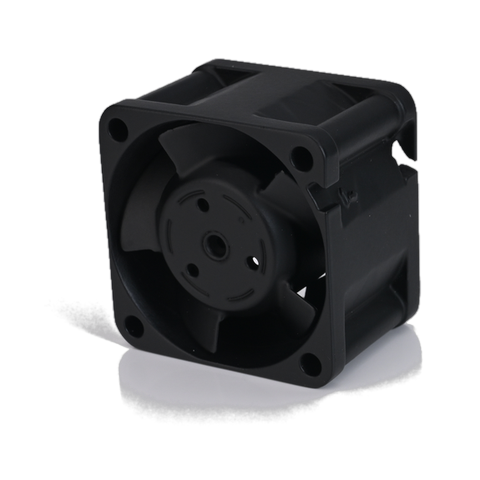
Perseus Minipro PCG36FZW522-28G-BB, a 40 mm x 40 mm x 28 mm 28 V DC axial cooling fan for shipboard electronics
The Minipro PCG36FZW522-28G-BB, a 40 x 40 x 28 mm 28 V DC axial fan. On a shipboard cabinet the frame size is fixed by the available mounting depth, so selection starts from the envelope and then moves to airflow and static pressure at the installed system curve.

Frequently Asked Questions

Q1. Can I use an avionics fan on a shipboard cabinet if it meets the temperature range?

Temperature range is the least demanding of the four loads. The obstacles are the continuous low-frequency vibration duty cycle, the salt-laden air path, and the difference between an airborne electrical bus and a ship's bus. An avionics fan may pass all three, but the specification has to establish that rather than assume it from the temperature figure. The specific checks are bearing type and sealing configuration, salt fog duration, and peak-current margin on the actual supply.

Q2. Is IP68 always better than IP67 for a naval fan?

No. IP68 is defined relative to an agreed depth and duration, and achieving it usually requires a sealing arrangement that changes airflow and may change the frame or bearing configuration. For spray, washdown, and short-term ingress, IP67 is the appropriate specification. Choose IP68 where flooding is a credible scenario, and re-run the thermal model when you do, because the sealed configuration is not airflow-equivalent to the IP67 one.

Q3. My cabinet already has an isolated frame. Do I still need fan isolators?

Often yes, because the frame isolates the cabinet from the ship, not the fan from the cabinet. The fan's own unbalance still excites the frame, and the fan still receives whatever the frame transmits. Whether separate fan mounts are worthwhile depends on the fan mass, the frame's structural modes, and whether a fan module with integrated isolation is available for that envelope. See the vibration isolation selection guide for the mounting-interface rules that apply at this level.

Q4. How much airflow margin should a shipboard fan carry?

Enough to cover three effects that all reduce flow over life: filter and screen loading, salt and corrosion deposits on blades and inlets, and the resistance added by the installed duct, louvre, and EMI screen. Sizing against a clean free-air figure carries zero margin against any of them. The margin should be set from the end-of-life system curve, and the operating point should be checked against the stall region at that condition, not only at commissioning.

Q5. What causes a fan to fail certification even though it passed vibration and salt fog separately?

The sequence. Vibration works seals, lead exits, and fasteners loose or out of position; salt fog then enters paths that were sealed when the unit was new. Running the tests in the order the equipment will experience them - vibration and shock first, then humidity and salt fog, then a functional check - exposes failures that a set of independent tests does not. This is also why the tested configuration must match the delivered configuration exactly.

Q6. Does a 400 Hz fan need a different motor, or just a different nameplate?

A different motor. A 50/60 Hz winding operated at 400 Hz has the wrong impedance and flux density, which produces overheating, acoustic noise, and starting problems. Fans built for military 400 Hz power are designed for that supply. Related electrical detail is covered in the EMC design note and the speed control note.

Q7. Can a COTS fan be used on a naval platform?

Often yes, and many programs do it - but "COTS" is a procurement label, not an environmental qualification. A commercial fan is acceptable exactly to the extent that the qualification evidence described above exists for it: a vibration report naming resonances, a shock grade matched to the mounting location, an IP rating qualified on the shipping configuration, and salt fog hours that support the platform's inspection interval. A COTS fan with that file is a lower-risk choice than a "military" fan without it. The label on the datasheet matters less than the test report behind it.


Conclusion

Naval cooling fans are specified by four loads, and a fan survives or fails on how those loads combine. Vibration endurance at a resonance the fan will actually sit on, shock at the grade the mounting location imposes, sealing that was qualified on the configuration that ships, and electrical margin against a bus that is not a bench supply - each is a separate requirement, and none of them substitutes for another.

The three rules worth carrying into a design review are these. Keep the fan's mounting natural frequency well below the lowest disturbing frequency, and check that the mount is rated for the fan's actual mass rather than its envelope. Size airflow against the end-of-life system curve with the installed duct, louvre, and screen in place, and keep the operating point clear of the stall region. And treat the fan as a source of excitation as well as a victim of it, because on a shipboard cabinet it is both.

For a specific platform, the useful next step is to compare the compartment's vibration and shock environment with the fan's mounted configuration rather than with a bare-unit datasheet. The small DC fan range, large DC fan range, centrifugal fan range and 400 Hz AC fan range cover the envelopes used in naval electronics cooling; the engineering team can review a specific compartment against them.

Written By

Perseus product image

Dr. Du

Dr. Du is a thermal engineering designer at Perseus, specializing in forced-air cooling design and high-static-pressure DC fan selection for military and defense electronics. He leads airflow configuration and fan curve optimization reviews for rugged cooling applications.